Technical Description
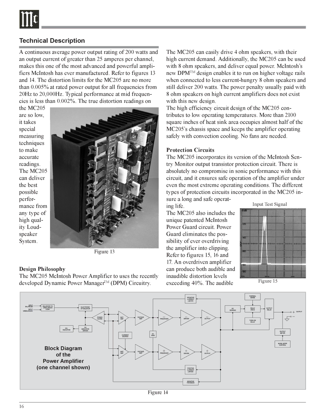
A continuous average power output rating of 200 watts and an output current of greater than 25 amperes per channel, makes this one of the most advanced and powerful ampli- fiers McIntosh has ever manufactured. Refer to figures 13 and 14. The distortion limits for the MC205 are no more than 0.005% at rated power output for all frequencies from 20Hz to 20,000Hz. Typical performance at mid frequen- cies is less than 0.002%. The true distortion readings on the MC205
are so low, it takes special measuring techniques to make accurate readings. The MC205 can deliver the best possible perfor- mance from any type of high qual- ity Loud- speaker System.
Figure 13
Design Philosophy
The MC205 McIntosh Power Amplifier to uses the recently developed Dynamic Power ManagerTM (DPM) Circuitry.
The MC205 can easily drive 4 ohm speakers, with their high current demand. Additionally, the MC205 can be used with 8 ohm speakers, and deliver equal power. McIntosh’s new DPMTM design enables it to run on higher voltage rails when connected to less
The high efficiency circuit design of the MC205 con- tributes to low operating temperatures. More than 2100 square inches of heat sink area occupies almost half of the MC205’s chassis space and keeps the amplifier operating safely with convection cooling. No fans are needed.
Protection Circuits
The MC205 incorporates its version of the McIntosh Sen- try Monitor output transistor protection circuit. There is absolutely no compromise in sonic performance with this circuit, and it ensures safe operation of the amplifier under even the most extreme operating conditions. The different types of protection circuits incorporated in the MC205 in- sure a long and safe operat-
ing life.
The MC205 also includes the unique patented McIntosh Power Guard circuit. Power Guard eliminates the pos- sibility of ever overdriving the amplifier into clipping. Refer to figures 15, 16 and
17.An overdriven amplifier can produce both audible and
inaudible distortion levels exceeding 40%. The audible
Block Diagram
of the
Power Amplifier
(one channel shown)
Figure 14
16
