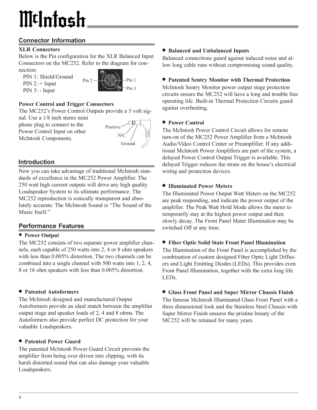
MC252 specifications
The McIntosh MC252 is a legendary power amplifier known for its innovative approach to high-fidelity audio reproduction. As a part of McIntosh's esteemed lineup, this amplifier embodies the company's commitment to exceptional sound quality and timeless design.One of the standout features of the MC252 is its dual mono design. This architecture not only enhances stereo imaging but also reduces crosstalk, providing a cleaner and more defined soundstage. Each channel operates independently, ensuring that each speaker receives precise and stable power, ideal for discerning audiophiles who demand the highest quality in their audio systems.
The MC252 is rated to deliver 250 watts per channel into 8 ohms, with a powerful peak at 300 watts into 4 ohms. This robust output makes it suitable for driving a wide range of speakers, from efficient bookshelf models to large floor-standing designs. The amplifier is designed to handle dynamic music and movie soundtracks with ease, delivering an engaging listening experience without distortion.
McIntosh's patented Power Guard technology is another hallmark feature of the MC252, designed to prevent clipping and distortion. This intelligent system monitors the output signal and automatically adjusts the power levels, ensuring the integrity of the audio signal is maintained even at high volumes. This feature guarantees that listeners can enjoy their music without fear of damaging their speakers.
The amplifier also incorporates a unique input and output circuitry that adheres to McIntosh’s time-honored values of craftsmanship and quality. The iconic blue watt meters not only serve a practical purpose, providing real-time feedback on power output but also add to the visual appeal of the unit, making it a centerpiece in any audio setup.
In terms of build quality, the MC252 features durable, high-quality aluminum and glass components that define McIntosh’s aesthetic. This attention to detail ensures longevity and a classic look that never goes out of style.
Overall, the McIntosh MC252 stands as a testament to the evolution of audio technology, offering robust performance, cutting-edge features, and a design ethos that honors tradition while embracing modernity. For audiophiles seeking a high-performance amplifier that delivers both power and finesse, the MC252 remains a compelling choice. Whether for home theater or music listening, its capabilities ensure an exceptional audio experience, making it a prized possession for any serious audio enthusiast.

