High-Speed I/O
R
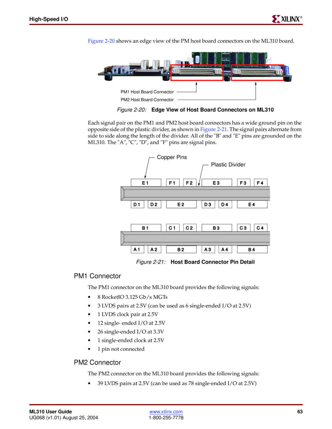
Figure 2-20 shows an edge view of the PM host board connectors on the ML310 board.
PM1 Host Board Connector
PM2 Host Board Connector
Figure 2-20: Edge View of Host Board Connectors on ML310
Each signal pair on the PM1 and PM2 host board connectors has a wide ground pin on the opposite side of the plastic divider, as shown in Figure
Copper Pins
Plastic Divider
E 1 | F 1 | F 2 | E 3 | F 3 | F 4 |
D 1
D 2
E 2
D 3
D 4
E 4
B 1
C 1
C 2
B 3
C 3
C 4
A 1
A 2
B 2
A 3
A 4
B 4
Figure 2-21: Host Board Connector Pin Detail
PM1 Connector
The PM1 connector on the ML310 board provides the following signals:
•8 RocketIO 3.125 Gb/s MGTs
•3 LVDS pairs at 2.5V (can be used as 6
•1 LVDS clock pair at 2.5V
•12 single- ended I/O at 2.5V
•26
•1
•1 pin not connected
PM2 Connector
The PM2 connector on the ML310 board provides the following signals:
•39 LVDS pairs at 2.5V (can be used as 78
ML310 User Guide | www.xilinx.com | 63 |
UG068 (v1.01) August 25, 2004 |
|