Board Hardware
R
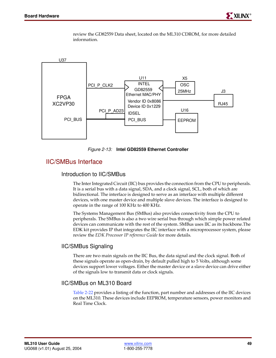
review the GD82559 Data sheet, located on the ML310 CDROM, for more detailed information.
U37
FPGA
XC2VP30
PCI_BUS
U11
PCI_P_CLK2INTEL GD82559
Ethernet MAC/PHY
Vendor ID 0x8086
Device ID 0x1229
PCI_P_AD23
IDSEL
PCI_BUS
X5
OSC 25MHz
U16
EEPROM
J3
RJ45
Figure 2-13: Intel GD82559 Ethernet Controller
IIC/SMBus Interface
Introduction to IIC/SMBus
The Inter Integrated Circuit (IIC) bus provides the connection from the CPU to peripherals. It is a serial bus with a data signal, SDA, and a clock signal, SCL, both of which are bidirectional. The interface is designed to serve as an interface with multiple different devices, with one master device and multiple slave devices. The interface is designed to operate in the range of 100 KHz to 400 KHz.
The Systems Management Bus (SMBus) also provides connectivity from the CPU to peripherals. The SMBus is also a two wire serial bus through which simple power related devices can communicate with the rest of the system. SMBus uses IIC as its backbone.The EDK kit provides IP that integrates the IIC interface with a microprocessor system, please review the EDK Processor IP reference Guide for more details.
IIC/SMBus Signaling
There are two main signals on the IIC Bus, the data signal and the clock signal. Both of these signals operate as
IIC/SMBus on ML310 Board
Table
ML310 User Guide | www.xilinx.com | 49 |
UG068 (v1.01) August 25, 2004 |
|
