R
Chapter 2: ML310 Embedded Development Platform
Parallel Cable IV Interface
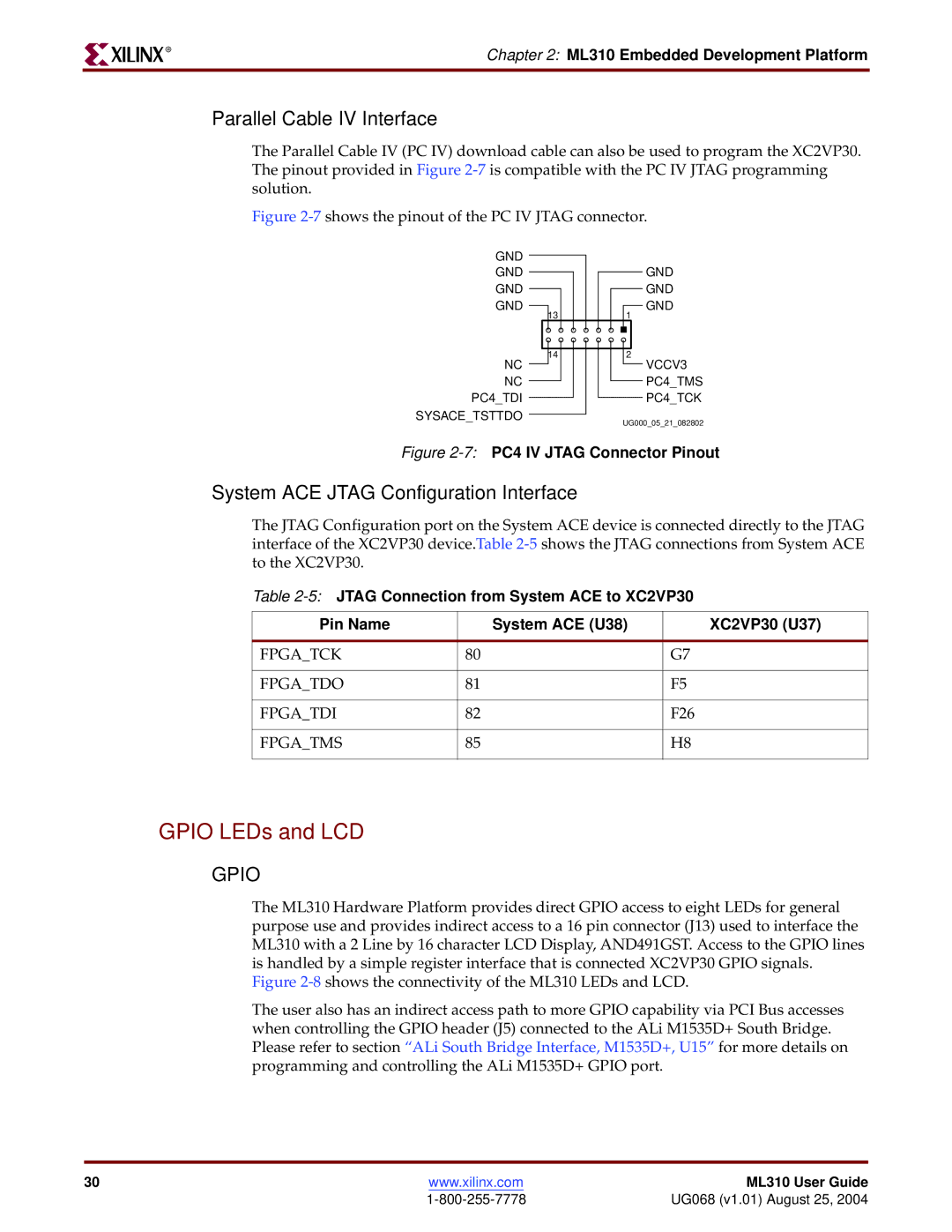
The Parallel Cable IV (PC IV) download cable can also be used to program the XC2VP30. The pinout provided in Figure
Figure 2-7 shows the pinout of the PC IV JTAG connector.
GND
GND
GND
GND
13
14
NC
NC
PC4_TDI
SYSACE_TSTTDO
GND
GND
GND
1
2
VCCV3
PC4_TMS
PC4_TCK
UG000_05_21_082802
Figure 2-7: PC4 IV JTAG Connector Pinout
System ACE JTAG Configuration Interface
The JTAG Configuration port on the System ACE device is connected directly to the JTAG interface of the XC2VP30 device.Table
Table
Pin Name |
| System ACE (U38) | XC2VP30 (U37) |
|
|
|
|
FPGA_TCK | 80 |
| G7 |
|
|
|
|
FPGA_TDO | 81 |
| F5 |
|
|
|
|
FPGA_TDI | 82 |
| F26 |
|
|
|
|
FPGA_TMS | 85 |
| H8 |
|
|
|
|
GPIO LEDs and LCD
GPIO
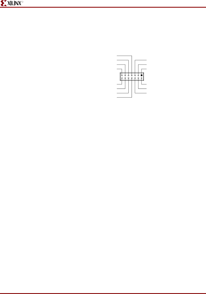
The ML310 Hardware Platform provides direct GPIO access to eight LEDs for general purpose use and provides indirect access to a 16 pin connector (J13) used to interface the ML310 with a 2 Line by 16 character LCD Display, AND491GST. Access to the GPIO lines is handled by a simple register interface that is connected XC2VP30 GPIO signals.
Figure 2-8 shows the connectivity of the ML310 LEDs and LCD.
The user also has an indirect access path to more GPIO capability via PCI Bus accesses when controlling the GPIO header (J5) connected to the ALi M1535D+ South Bridge. Please refer to section “ALi South Bridge Interface, M1535D+, U15” for more details on programming and controlling the ALi M1535D+ GPIO port.
30 | www.xilinx.com | ML310 User Guide |
| UG068 (v1.01) August 25, 2004 |