R
Chapter 2: ML310 Embedded Development Platform
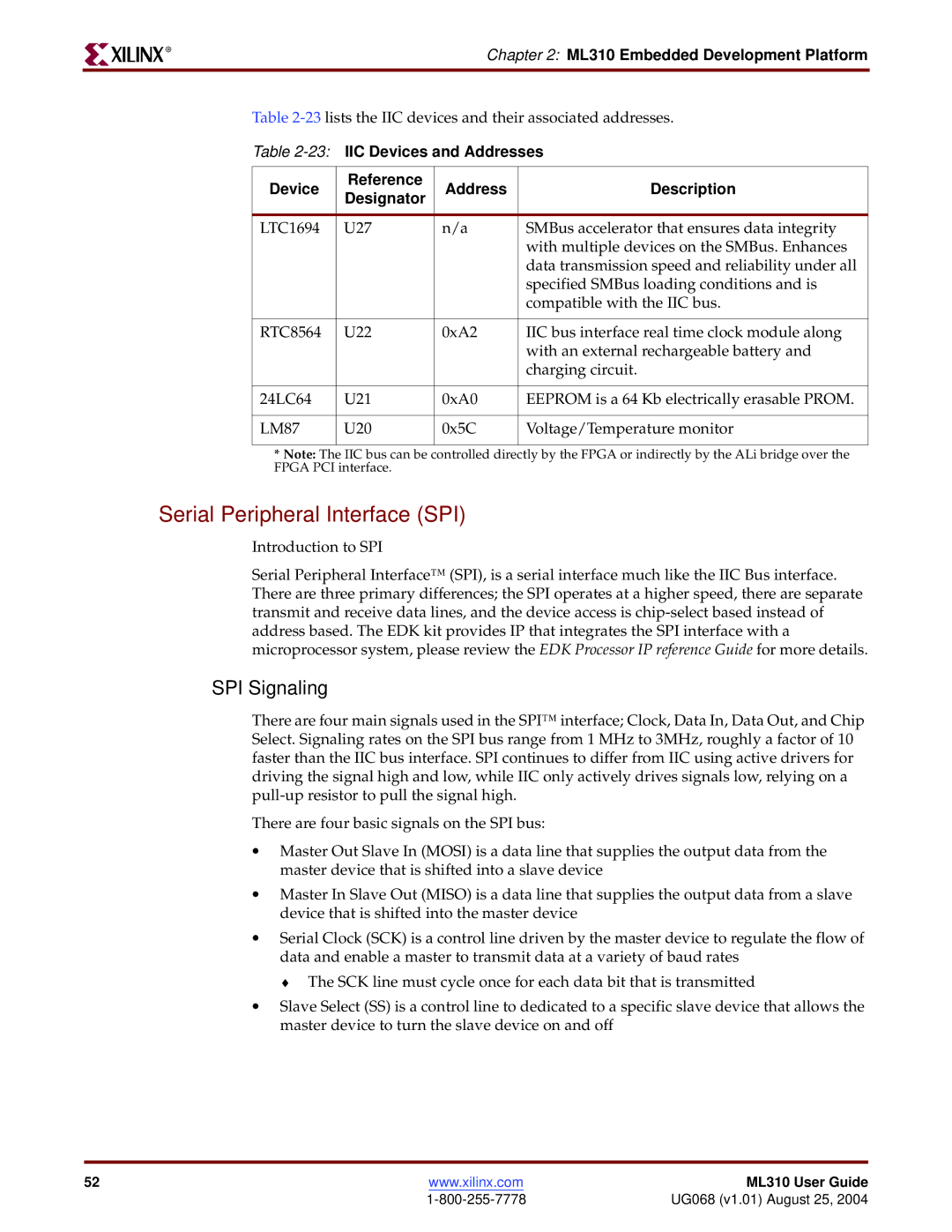
Table
Table
Device | Reference | Address | Description | |
Designator | ||||
|
|
| ||
|
|
|
| |
LTC1694 | U27 | n/a | SMBus accelerator that ensures data integrity | |
|
|
| with multiple devices on the SMBus. Enhances | |
|
|
| data transmission speed and reliability under all | |
|
|
| specified SMBus loading conditions and is | |
|
|
| compatible with the IIC bus. | |
|
|
|
| |
RTC8564 | U22 | 0xA2 | IIC bus interface real time clock module along | |
|
|
| with an external rechargeable battery and | |
|
|
| charging circuit. | |
|
|
|
| |
24LC64 | U21 | 0xA0 | EEPROM is a 64 Kb electrically erasable PROM. | |
|
|
|
| |
LM87 | U20 | 0x5C | Voltage/Temperature monitor | |
|
|
|
|
*Note: The IIC bus can be controlled directly by the FPGA or indirectly by the ALi bridge over the FPGA PCI interface.
Serial Peripheral Interface (SPI)
Introduction to SPI
Serial Peripheral Interface™ (SPI), is a serial interface much like the IIC Bus interface. There are three primary differences; the SPI operates at a higher speed, there are separate transmit and receive data lines, and the device access is
SPI Signaling
There are four main signals used in the SPI™ interface; Clock, Data In, Data Out, and Chip Select. Signaling rates on the SPI bus range from 1 MHz to 3MHz, roughly a factor of 10 faster than the IIC bus interface. SPI continues to differ from IIC using active drivers for driving the signal high and low, while IIC only actively drives signals low, relying on a
There are four basic signals on the SPI bus:
•Master Out Slave In (MOSI) is a data line that supplies the output data from the master device that is shifted into a slave device
•Master In Slave Out (MISO) is a data line that supplies the output data from a slave device that is shifted into the master device
•Serial Clock (SCK) is a control line driven by the master device to regulate the flow of data and enable a master to transmit data at a variety of baud rates
♦ The SCK line must cycle once for each data bit that is transmitted
•Slave Select (SS) is a control line to dedicated to a specific slave device that allows the master device to turn the slave device on and off
52 | www.xilinx.com | ML310 User Guide |
| UG068 (v1.01) August 25, 2004 |