Board Hardware
R
SPI Addressing
The SPI does not use an addressed based system like the IIC Bus Interface uses. Instead, devices are selected by dedicated Slave Select signals, comparable to a Chip Select signal. Each SPI Slave device needs its own Slave Select signal driven from the SPI master. This increases the total pin count, but decreases overhead and complexity, which increases the available bandwidth and decreases bus contention.
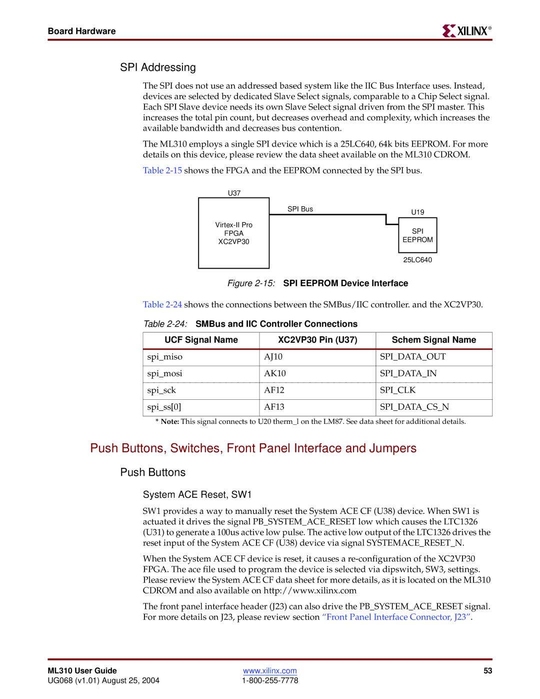
The ML310 employs a single SPI device which is a 25LC640, 64k bits EEPROM. For more details on this device, please review the data sheet available on the ML310 CDROM.
Table
U37
FPGA
XC2VP30
SPI Bus | U19 |
|
SPI
EEPROM
25LC640
Figure 2-15: SPI EEPROM Device Interface
Table
Table
UCF Signal Name | XC2VP30 Pin (U37) | Schem Signal Name |
|
|
|
spi_miso | AJ10 | SPI_DATA_OUT |
|
|
|
spi_mosi | AK10 | SPI_DATA_IN |
|
|
|
spi_sck | AF12 | SPI_CLK |
|
|
|
spi_ss[0] | AF13 | SPI_DATA_CS_N |
|
|
|
*Note: This signal connects to U20 therm_l on the LM87. See data sheet for additional details.
Push Buttons, Switches, Front Panel Interface and Jumpers
Push Buttons
System ACE Reset, SW1
SW1 provides a way to manually reset the System ACE CF (U38) device. When SW1 is actuated it drives the signal PB_SYSTEM_ACE_RESET low which causes the LTC1326 (U31) to generate a 100us active low pulse. The active low output of the LTC1326 drives the reset input of the System ACE CF (U38) device via signal SYSTEMACE_RESET_N.
When the System ACE CF device is reset, it causes a
The front panel interface header (J23) can also drive the PB_SYSTEM_ACE_RESET signal. For more details on J23, please review section “Front Panel Interface Connector, J23”.
ML310 User Guide | www.xilinx.com | 53 |
UG068 (v1.01) August 25, 2004 |
|
