Board Hardware
R
Note: An Antec, model SL250S, ATX Power Supply is delivered with your ML310. The Antec User’s Manual is provided in the Data sheets section on the ML310 CDROM. Prior to installation please read the Installation section of the Antec User’s Manual which describes the red voltage switch power setting on your Antec SL250S supply.
Check the red power supply voltage switch setting before installation. It should be the same as your local power voltage (115V for North America, Japan, etc. and 230V for Europe and many other countries). Change the voltage setting if necessary. Failure to take this precaution could result in damage to your equipment and could void your warranty.
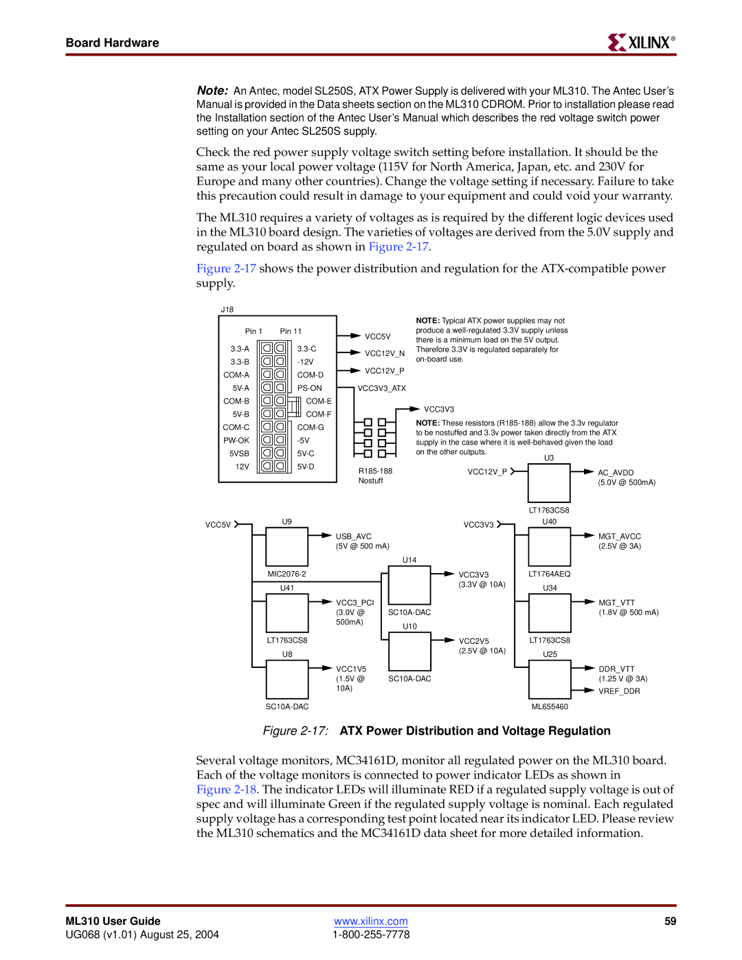
The ML310 requires a variety of voltages as is required by the different logic devices used in the ML310 board design. The varieties of voltages are derived from the 5.0V supply and regulated on board as shown in Figure
Figure 2-17 shows the power distribution and regulation for the ATX-compatible power supply.
J18 |
|
|
|
|
|
|
|
|
|
| |
|
|
|
|
|
|
|
| NOTE: Typical ATX power supplies may not |
| ||
Pin 1 | Pin 11 |
| VCC5V | produce a |
| ||||||
|
|
|
| there is a minimum load on the 5V output. |
| ||||||
|
|
|
|
|
|
|
|
| |||
| VCC12V_N | Therefore 3.3V is regulated separately for |
| ||||||||
|
|
|
| ||||||||
|
|
|
|
|
|
|
| ||||
|
|
|
|
|
|
|
|
| |||
| VCC12V_P |
|
|
|
| ||||||
|
|
|
|
| |||||||
|
|
|
|
|
|
|
|
| |||
| VCC3V3_ATX |
|
|
|
| ||||||
|
|
|
|
| |||||||
|
|
|
|
| VCC3V3 |
|
|
| |||
|
|
|
|
|
|
|
| ||||
|
|
|
|
|
|
|
| ||||
|
|
|
|
| NOTE: These resistors | ||||||
|
|
|
|
| |||||||
|
|
|
|
| |||||||
|
|
|
|
| to be nostuffed and 3.3v power taken directly from the ATX | ||||||
|
|
|
|
| |||||||
|
|
|
|
| supply in the case where it is | ||||||
|
|
|
|
| |||||||
5VSB |
|
|
|
|
| on the other outputs. |
| U3 |
| ||
12V |
| VCC12V_P |
| AC_AVDD | |||||||
|
|
| |||||||||
|
|
|
|
|
| ||||||
|
|
|
| Nostuff |
|
|
| (5.0V @ 500mA) | |||
|
|
|
|
|
|
|
|
|
| LT1763CS8 |
|
VCC5V | U9 |
|
|
|
|
| VCC3V3 |
| U40 |
| |
|
|
|
|
|
|
|
|
| |||
|
|
| USB_AVC |
|
|
| MGT_AVCC | ||||
|
|
|
|
|
| ||||||
|
|
| (5V @ 500 mA) |
|
|
| (2.5V @ 3A) | ||||
|
|
|
|
|
|
| U14 |
|
|
| |
U41
![]() VCC3_PCI (3.0V @ 500mA)
VCC3_PCI (3.0V @ 500mA)
LT1763CS8
U8
![]() VCC1V5 (1.5V @ 10A)
VCC1V5 (1.5V @ 10A)
|
| VCC3V3 | LT1764AEQ | |||
| ||||||
|
| (3.3V @ 10A) |
| U34 | ||
|
|
|
| |||
|
|
|
|
|
| MGT_VTT |
|
|
|
| |||
|
|
| (1.8V @ 500 mA) | |||
|
| U10 |
|
|
|
|
|
| VCC2V5 |
| LT1763CS8 | ||
|
|
| ||||
|
| (2.5V @ 10A) |
| U25 | ||
|
|
|
| |||
|
|
|
|
|
| DDR_VTT |
|
|
| (1.25 V @ 3A) | |||
|
|
|
|
|
| VREF_DDR |
|
|
|
|
|
| |
|
|
|
| ML655460 | ||
Figure 2-17: ATX Power Distribution and Voltage Regulation
Several voltage monitors, MC34161D, monitor all regulated power on the ML310 board. Each of the voltage monitors is connected to power indicator LEDs as shown in
Figure 2-18. The indicator LEDs will illuminate RED if a regulated supply voltage is out of spec and will illuminate Green if the regulated supply voltage is nominal. Each regulated supply voltage has a corresponding test point located near its indicator LED. Please review the ML310 schematics and the MC34161D data sheet for more detailed information.
ML310 User Guide | www.xilinx.com | 59 |
UG068 (v1.01) August 25, 2004 |
|