Technical Description, con’t
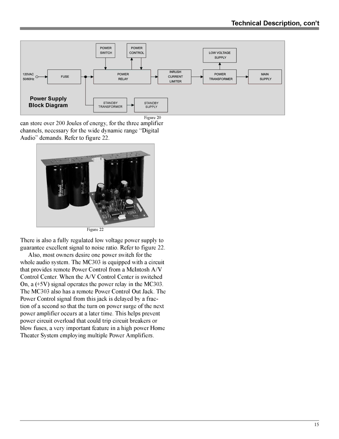
Power Supply | STANDBY | STANDBY | |
Block Diagram | |||
TRANSFORMER | SUPPLY | ||
|
| Figure 20 |
can store over 200 Joules of energy, for the three amplifier channels, necessary for the wide dynamic range “Digital Audio” demands. Refer to figure 22.
Figure 22
There is also a fully regulated low voltage power supply to guarantee excellent signal to noise ratio. Refer to figure 22.
Also, most owners desire one power switch for the whole audio system. The MC303 is equipped with a circuit that provides remote Power Control from a McIntosh A/V Control Center. When the A/V Control Center is switched On, a (+5V) signal operates the power relay in the MC303. The MC303 also has a remote Power Control Out Jack. The Power Control signal from this jack is delayed by a frac- tion of a second so that the turn on power surge of the next power amplifier occurs at a later time. This helps prevent power circuit overload that could trip circuit breakers or blow fuses, a very important feature in a high power Home Theater System employing multiple Power Amplifiers.
15