– 13 – |
| ||
position. Then, if necessary, make adjustments to these 3 |
| ||
Remove | |||
screws to refine the | |||
mirror can be seen centered within the diagonal mirror reflection. When the | adhesive | ||
backing | |||
diagonal mirror is correctly aligned, it will look like Fig. 9. (Note: the primary | |||
| |||
mirror is shown out of alignment.) | 2 | ||
|
| ||
c. Primary mirror adjustments | 1 | ||
| |||
If the diagonal mirror (1, Fig. 9) and the reflection of the primary mirror (2, |
| ||
Fig. 9) appear centered within the drawtube (3, Fig. 9), but the reflection of |
| ||
| |||
your eye and the reflection of the diagonal mirror (4, Fig. 9) appear off- |
| Fig. 5: Diagonal Assembly. | |
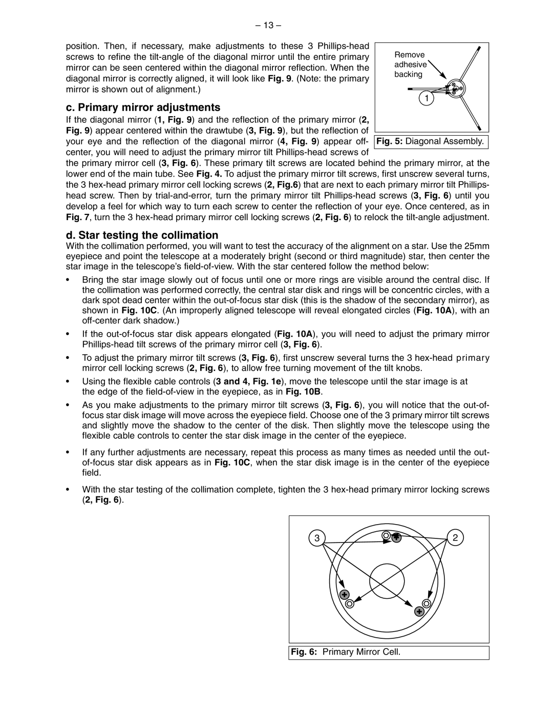
center, you will need to adjust the primary mirror tilt |
|
| |
|
| ||
the primary mirror cell (3, Fig. 6). These primary tilt screws are located behind the primary mirror, at the lower end of the main tube. See Fig. 4. To adjust the primary mirror tilt screws, first unscrew several turns, the 3
d. Star testing the collimation
With the collimation performed, you will want to test the accuracy of the alignment on a star. Use the 25mm eyepiece and point the telescope at a moderately bright (second or third magnitude) star, then center the star image in the telescope’s
•Bring the star image slowly out of focus until one or more rings are visible around the central disc. If the collimation was performed correctly, the central star disk and rings will be concentric circles, with a dark spot dead center within the
•If the
•To adjust the primary mirror tilt screws (3, Fig. 6), first unscrew several turns the 3
•Using the flexible cable controls (3 and 4, Fig. 1e), move the telescope until the star image is at the edge of the
•As you make adjustments to the primary mirror tilt screws (3, Fig. 6), you will notice that the
•If any further adjustments are necessary, repeat this process as many times as needed until the out-
•With the star testing of the collimation complete, tighten the 3
3![]()
![]() 2
2