INTRODUCTION
Before you begin, we urge you to take a few minutes to completely read this manual so that you can get the best use of the equipment. This manual details the
STANDARD EQUIPMENT (Refer to Fig. 1)
•Complete optical tube assembly (objective lens diameter = 60mm; focal length = 700mm)
•
•MA25mm (28X), MH9mm eyepieces (1.25" O.D. “Outside Diameter”)
•2x Barlow Lens (1.25" O.D.)
•Diagonal mirror (1.25" O.D.)
•5 x 24mm viewfinder with bracket
•Altazimuth mount with
•Hardware package: A. 3 bolts (2" long) with wing nuts and washers
B. 3 screws (1/2" long) with nuts
Note: All other necessary hardware provided in place.
UNPACKING AND ASSEMBLY
You will need a
1.Remove and identify the telescope’s components, using the listing above.
2.Attach the 3 aluminum tripod legs (7, Fig. 1) to the base of the altazimuth mount (10, Fig. 1) with the 3 leg brace supports (8, Fig. 1) facing inward. Line up the holes of the tripod legs (11, Fig. 1) with the holes on the mount base attachment and thread the three included bolts through the holes. Thread the wing nuts over the bolts and
3.To attach the leg braces to the tripod, line up the holes in the leg braces (9, Fig. 1) with the holes in the leg brace supports (8, Fig. 1) and slide the the included 1/2” screws through the holes. Thread the included nuts over the end of the bolts and
4.To attach the accessory tray (26, Fig. 1) to the leg braces (9, Fig. 1), place the round accessory tray over the over mounting bolt hole (12, Fig. 1). Thread the attachment knob into the mounting hole on top of the tray and turning the knob clockwise. Tighten to a firm feel, but do not
5.Extend the sliding center portion of the adjustable height tripod leg (19, Fig. 1) to the desired length for all 3 legs. Lock the tripod legs by tightening the leg lock thumbscrew (20, Fig. 1) to a firm feel. See Inset B.
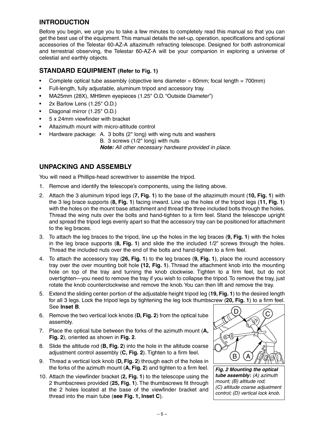
6. | Remove the two vertical lock knobs (D, Fig. 2) from the optical tube | D | C | |
| ||||
| assembly. |
|
| |
7. | Place the optical tube between the forks of the azimuth mount (A, |
|
| |
| Fig. 2), oriented as shown in Fig. 2. |
|
| |
8. | Slide the altitude rod (B, Fig. 2) into the hole in the altitude coarse |
|
| |
| adjustment control assembly (C, Fig. 2). Tighten to a firm feel. | B | A | |
9. | Thread a vertical lock knob (D, Fig. 2) through each of the holes in | |||
|
| |||
| the forks of the azimuth mount (A, Fig. 2) and tighten to a firm feel. | Fig. 2 Mounting the optical | ||
|
| |||
10. | Attach the viewfinder bracket (2, Fig. 1) to the telescope using the | tube assembly: (A) azimuth | ||
| 2 thumbscrews provided (25, Fig. 1). The thumbscrews fit through | mount; (B) altitude rod; | ||
| the 2 holes located at the base of the viewfinder bracket and | (C) altitude coarse adjustment | ||
| control; (D) vertical lock knob. | |||
| thread into the main tube (see Fig. 1, Inset C). | |||
|
|
| ||
– 5 –