Functional Details |
Screw terminal wiring
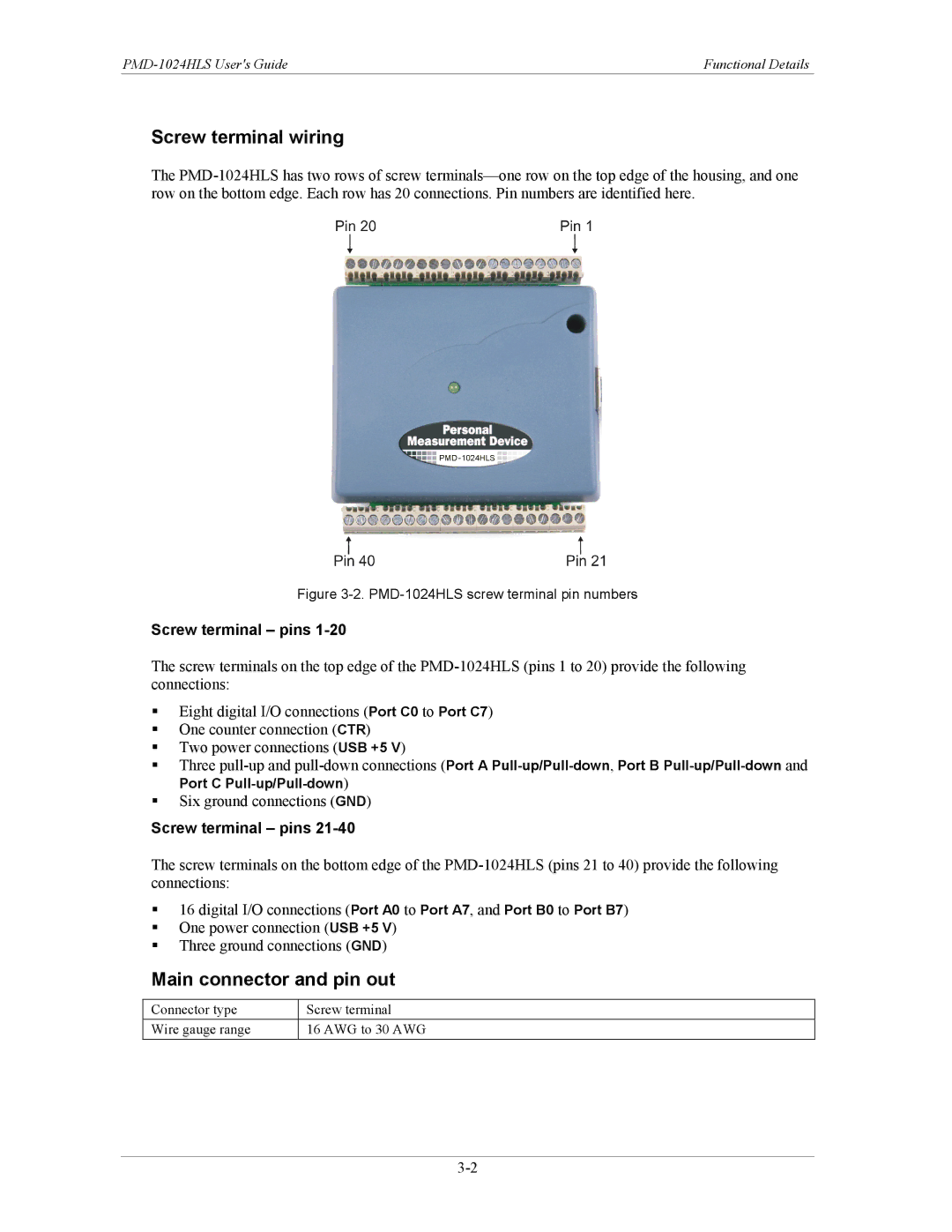
The
Figure 3-2. PMD-1024HLS screw terminal pin numbers
Screw terminal – pins 1-20
The screw terminals on the top edge of the
Eight digital I/O connections (Port C0 to Port C7)
One counter connection (CTR)
Two power connections (USB +5 V)
Three
Six ground connections (GND)
Screw terminal – pins
The screw terminals on the bottom edge of the
16 digital I/O connections (Port A0 to Port A7, and Port B0 to Port B7)
One power connection (USB +5 V)
Three ground connections (GND)
Main connector and pin out
Connector type | Screw terminal |
Wire gauge range | 16 AWG to 30 AWG |