|
|
|
|
| Functional Details |
|
|
| |||
CTR GND GND GND GND Port A | USB +5 V Port B | GND Port C | Port C6 | Port C5 Port C4 Port C3 Port C2 Port C1 Port C0 | |
20 19 18 17 16 15 | 14 13 | 12 11 | 10 9 8 | 7 | 6 5 4 3 2 1 |
Port A0 21
Port A1 22
Port A2 23
Port A3 24
Port A4 25
Port A5 26
Port A6 27
Port A7 28
GND 29
USB +5 V 30
GND 31
Port B0 32
Port B1 33
Port B2 34
Port B3 35
Port B4 36
Port B5 37
Port B6 38
Port B7 39
GND 40
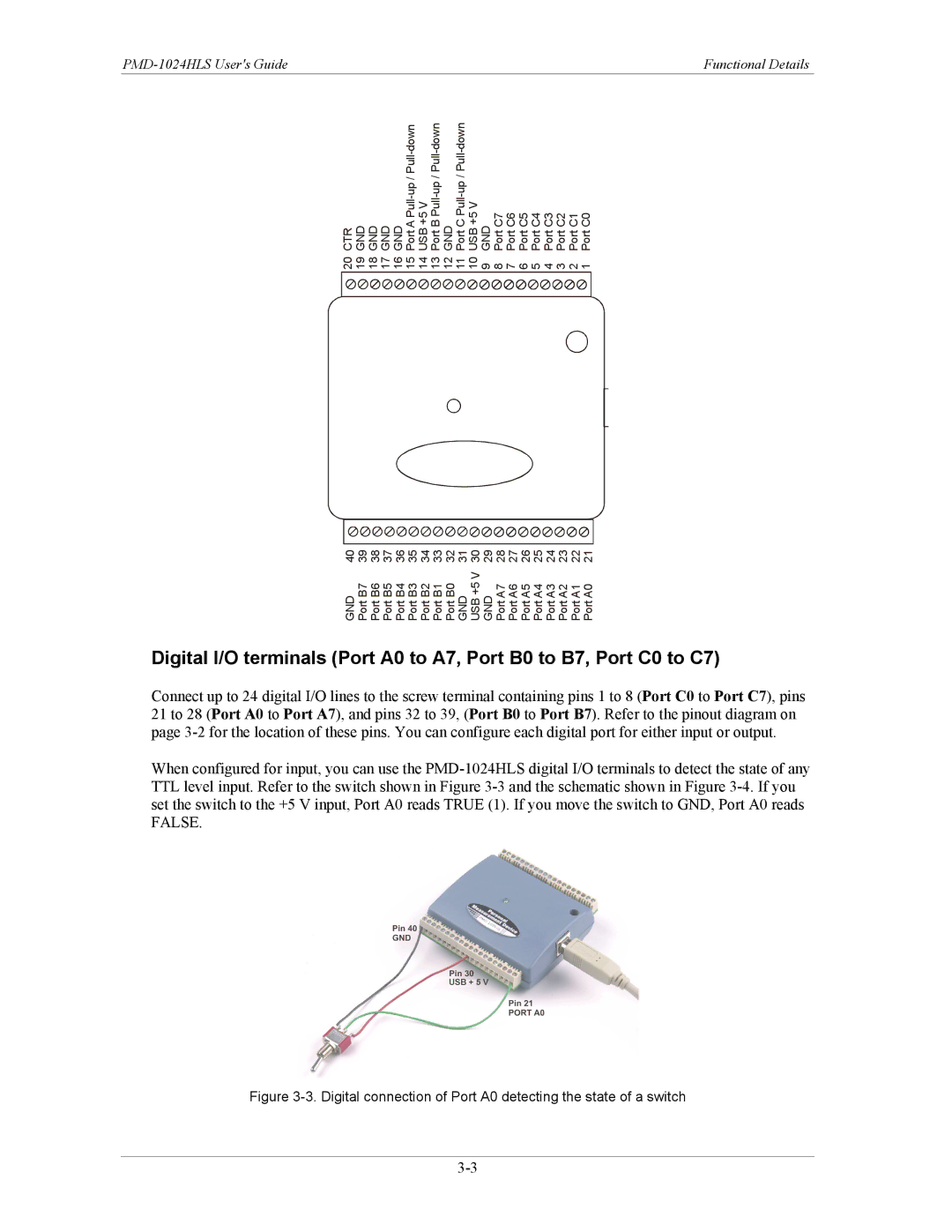
Digital I/O terminals (Port A0 to A7, Port B0 to B7, Port C0 to C7)
Connect up to 24 digital I/O lines to the screw terminal containing pins 1 to 8 (Port C0 to Port C7), pins 21 to 28 (Port A0 to Port A7), and pins 32 to 39, (Port B0 to Port B7). Refer to the pinout diagram on page
When configured for input, you can use the