5
Assembly Instructions
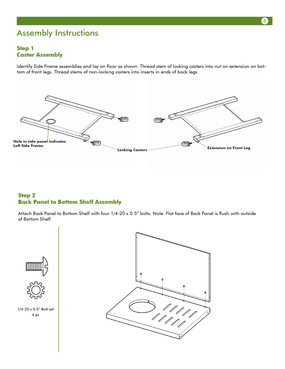
Step 1
Caster Assembly
Identify Side Frame assemblies and lay on floor as shown. Thread stem of locking casters into nut on extension on bot- tom of front legs. Thread stems of
Hole in side panel indicates |
|
|
Left Side Frame. | Locking Casters | Extension on Front Leg |
| ||
|
|
Step 2
Back Panel to Bottom Shelf Assembly
Attach Back Panel to Bottom Shelf with four
4 pc