ALL VEHICLES
1
3
1½"
3/8"
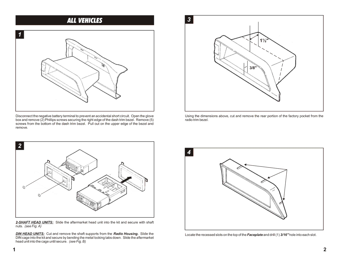
Disconnect the negative battery terminal to prevent an accidental short circuit. Open the glove box and remove (2) Phillips screws securing the right edge of the dash trim bezel. Remove (5) screws from the bottom of the dash trim bezel. Pull out on the upper edge of the bezel and remove.
2
nuts. (see Fig. A)
DIN HEAD UNITS: Cut and remove the shaft supports from the Radio Housing. Slide the DIN cage into the kit and secure by bending the metal locking tabs down. Slide the aftermarket head unit into the cage until secure. (see Fig. B)
1
Using the dimensions above, cut and remove the rear portion of the factory pocket from the radio trim bezel.
4
Locate the recessed slots on the top of the Faceplate and drill (1) 3/16" hole into each slot.
2
