5
A
B
C |
D
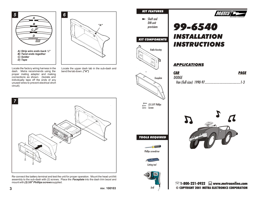
A)Strip wire ends back ½"
B)Twist ends together
C)Solder
D)Tape
6
"A"
KIT FEATURES
Shaft and DIN unit provisions
KIT COMPONENTS
Radio Housing
99-6540
INSTALLATION
INSTRUCTIONS
Locate the factory wiring harness in the | Locate the upper dash tab in the |
dash. Metra recommends using the | bend the tab down. ("A") |
proper mating adaptor and making |
|
connections as shown. (Isolate and |
|
individually tape off the ends of any |
|
unused wires to prevent electrical short |
|
circuit). |
|
7
3 | rev. 100103 |
Faceplate
![]() (3) 3/8" Phillips
(3) 3/8" Phillips
![]() Screws
Screws
TOOLS REQUIRED
Phillips screwdriver
Cutting tool
Drill
APPLICATIONS |
|
CAR | PAGE |
DODGE |
|
Van (full size) |
![]()
![]() www.metraonline.com
www.metraonline.com
© COPYRIGHT 2001 METRA ELECTRONICS CORPORATION