Installation Guide
Follow the simple steps outlined in this section to install and start using the
R104.
NOTE: Electrostatic discharge precautions should be taken when handling any circuit board. Proper grounding is recommended (i.e., wear a wrist strap).
1Unpack the Line Card
Your order has been provided with the safest possible packaging, but shipping damage does occasionally occur. Inspect your card carefully. If you discover any shipping damage, notify your carrier and follow their instructions for damage and claims. Save the original shipping carton if return or storage of the unit is necessary.
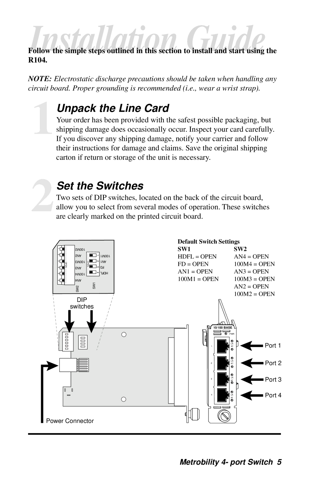
2Set the Switches
Two sets of DIP switches, located on the back of the circuit board, allow you to select from several modes of operation. These switches are clearly marked on the printed circuit board.
1 2 3 4 5 6![]()

100M2 |
|
|
|
|
|
|
|
|
AN2 |
|
|
|
| 1234 | HDFL | ||
|
|
|
|
|
|
| 100M1 | |
100M3 |
|
|
|
|
|
|
| AN1 |
|
|
|
|
|
|
| ||
AN3 |
|
|
|
|
|
|
| FD |
|
|
|
|
|
|
| ||
100M4 |
|
|
|
|
|
|
|
|
AN4 |
|
|
| SW1 |
| |||
SW2 |
|
|
|
| ||||
DIP
switches
Default Switch Settings
SW1 |
| SW2 |
HDFL = OPEN |
| AN4 = OPEN |
FD = OPEN |
| 100M4 = OPEN |
AN1 = OPEN |
| AN3 = OPEN |
100M1 = OPEN |
| 100M3 = OPEN |
|
| AN2 = OPEN |
|
| 100M2 = OPEN |
10/100 BASE |
| |
| PWR | |
| LK | Port 1 |
1 | AT | |
| LK | Port 2 |
2 | AT | |
3 | LK | Port 3 |
AT |
| |
|
| |
4 | AT | Port 4 |
LK |
| |
Power Connector