Versions “11” and “24” Pin Assignments for RS-485
The version “11” and “24” scanners head cables are terminated with a male
The version “11” and “24” scanners are designed to be used primarily with IBM® 46XX series of electronic cash registers. It can also be configured to communicate using the full
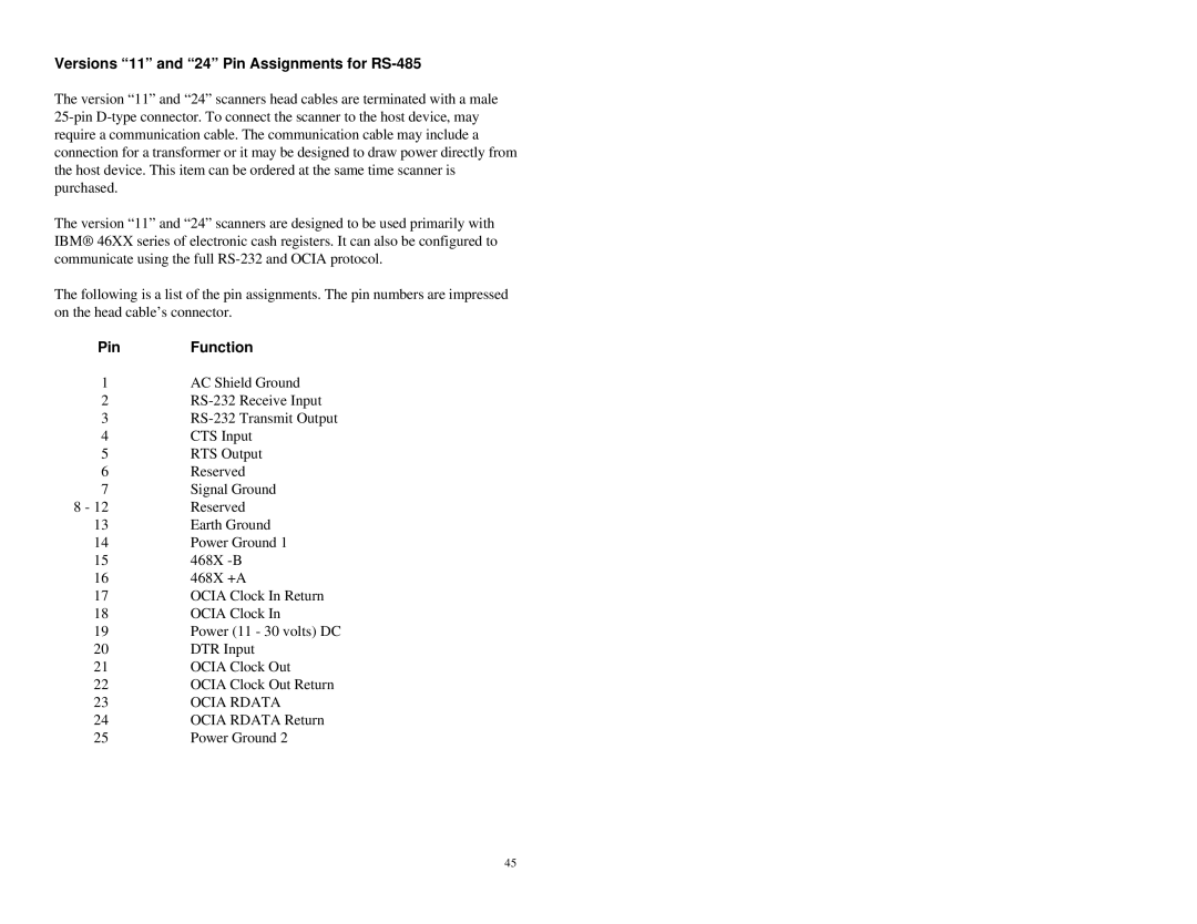
The following is a list of the pin assignments. The pin numbers are impressed on the head cable’s connector.
Pin | Function |
1 | AC Shield Ground |
2 | |
3 | |
4 | CTS Input |
5 | RTS Output |
6 | Reserved |
7 | Signal Ground |
8 - 12 | Reserved |
13 | Earth Ground |
14 | Power Ground 1 |
15 | 468X |
16 | 468X +A |
17 | OCIA Clock In Return |
18 | OCIA Clock In |
19 | Power (11 - 30 volts) DC |
20 | DTR Input |
21 | OCIA Clock Out |
22 | OCIA Clock Out Return |
23 | OCIA RDATA |
24 | OCIA RDATA Return |
25 | Power Ground 2 |
45
