Version “15” Pin Assignments for Light Pen Emulation
Each TECH 7 scanner has a
The Version “15” scanner is designed to be used for Light Pen Emulation communication.
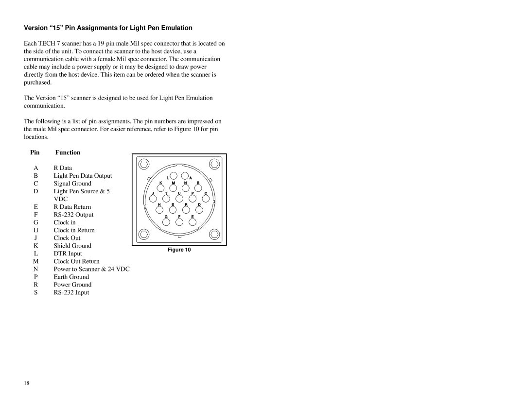
The following is a list of pin assignments. The pin numbers are impressed on the male Mil spec connector. For easier reference, refer to Figure 10 for pin locations.
Pin | Function |
|
| |||
|
|
|
|
| ||
A | R Data |
|
|
|
| |
|
|
|
|
| ||
|
|
|
| |||
B | Light Pen Data Output |
|
|
|
|
|
C | Signal Ground |
|
|
|
|
|
D | Light Pen Source & 5 |
|
|
|
|
|
| VDC |
|
|
|
|
|
|
|
|
|
|
| |
E | R Data Return |
|
|
|
|
|
F |
|
|
|
|
| |
G | Clock in |
|
|
|
|
|
H | Clock in Return |
|
|
|
|
|
J | Clock Out |
|
|
|
|
|
K | Shield Ground |
|
| |||
|
| |||||
L |
|
| Figure 10 | |||
DTR Input | ||||||
M | Clock Out Return | |||||
NPower to Scanner & 24 VDC
P Earth Ground
R Power Ground
S
18