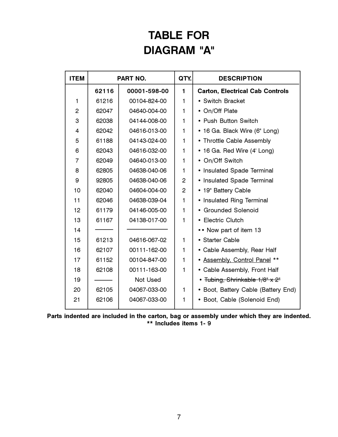
TABLE FOR
DIAGRAM "A"
ITEM |
|
|
|
|
| PART NO. | QTY. | DESCRIPTION |
| |||
|
|
|
|
|
|
|
|
|
|
|
|
|
| 62116 |
|
| 1 | Carton, Electrical Cab Controls |
| ||||||
1 | 61216 |
|
|
| 1 | • Switch Bracket |
| |||||
2 | 62047 |
|
|
| 1 | • On/Off Plate |
| |||||
3 | 62038 |
|
|
| 1 | • Push Button Switch |
| |||||
4 | 62042 |
|
|
| 1 | • 16 Ga. Black Wire (6" Long) |
| |||||
5 | 61188 |
|
|
| 1 | • Throttle Cable Assembly |
| |||||
6 | 62043 |
|
|
| 1 | • 16 Ga. Red Wire (4' Long) |
| |||||
7 | 62049 |
|
|
| 1 | • On/Off Switch |
| |||||
8 | 62805 |
|
|
| 1 | • Insulated Spade Terminal |
| |||||
9 | 92805 |
|
|
| 2 | • Insulated Spade Terminal |
| |||||
10 | 62040 |
|
|
| 2 | • 19" Battery Cable |
| |||||
11 | 62046 |
|
|
| 1 | • Insulated Ring Terminal |
| |||||
12 | 61179 |
|
|
| 1 | • Grounded Solenoid |
| |||||
13 | 61167 |
|
|
| 1 | • Electric Clutch |
| |||||
14 |
|
|
|
|
|
|
|
|
|
| •• Now part of item 13 |
|
|
|
|
|
|
|
|
|
|
|
| ||
15 | 61213 |
|
|
| 1 | • Starter Cable |
| |||||
16 | 62107 |
|
|
| 1 | • Cable Assembly, Rear Half |
| |||||
17 | 61152 |
|
|
| 1 | • Assembly, Control Panel ** |
| |||||
18 | 62108 |
|
|
| 1 | • Cable Assembly, Front Half |
| |||||
19 |
|
|
|
|
|
|
| Not Used |
| • Tubing, Shrinkable 1/8" x 2" |
| |
|
|
|
|
|
|
|
|
| ||||
20 | 62105 |
|
|
| 1 | • Boot, Battery Cable (Battery End) |
| |||||
21 | 62106 |
|
|
| 1 | • Boot, Cable (Solenoid End) |
| |||||
|
|
|
|
|
|
|
|
|
|
|
|
|
Parts indented are included in the carton, bag or assembly under which they are indented.
** Includes items 1- 9
7