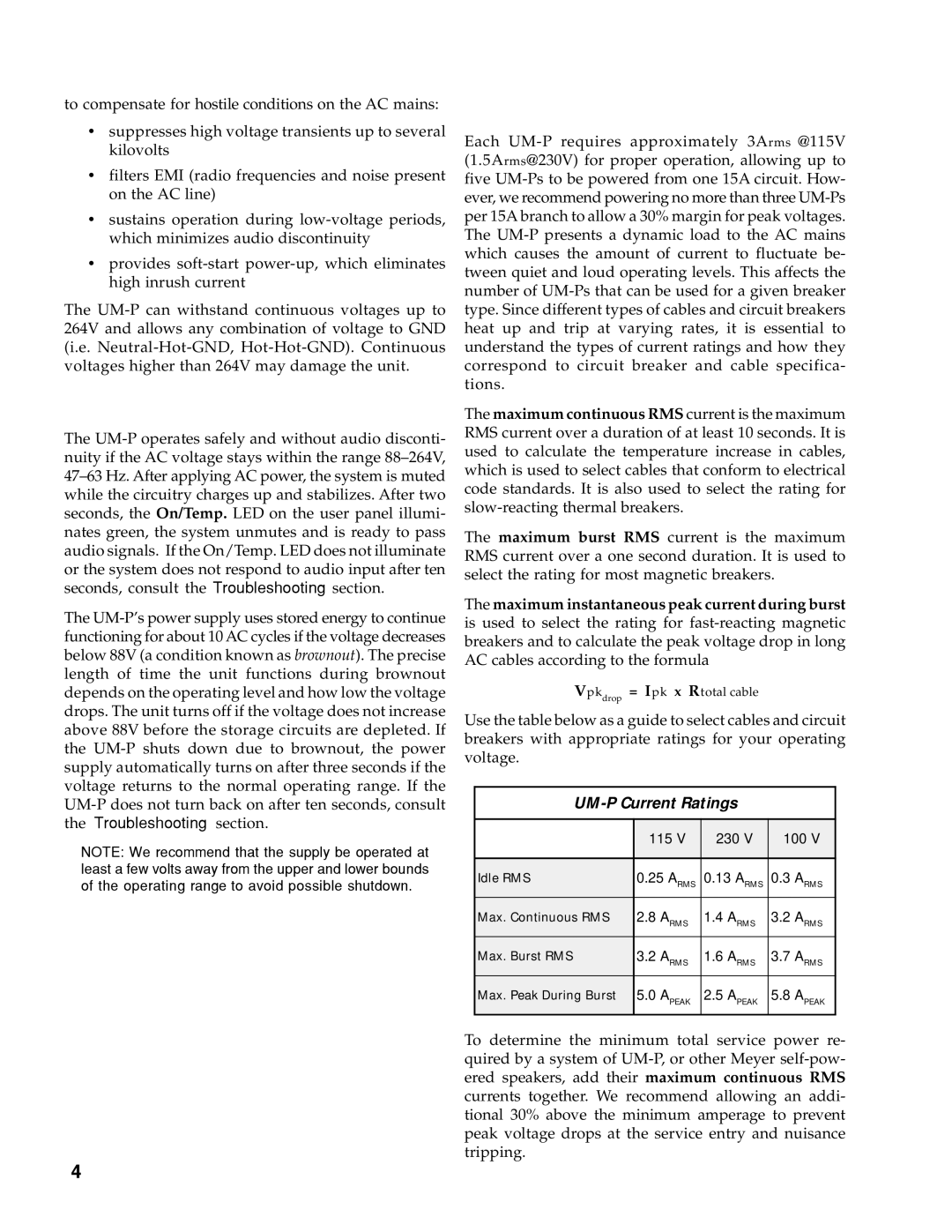
UM-100P, UM-1P specifications
Meyer Sound, a leader in professional audio technology, has produced a range of high-performance stage monitors, among which the UM-1P and UM-100P models stand out for their exceptional sound fidelity and robust design. These monitors are engineered to deliver precise audio reproduction, making them ideal for live performances, studio recordings, and various sound reinforcement applications.The Meyer Sound UM-1P is a self-powered, wide-range stage monitor that excels in providing a stable and consistent sound quality. Its compact, low-profile design ensures that it fits well in any stage setting while also maintaining visual appeal. One of its key features is the proprietary high-frequency compression driver, which allows for incredible clarity and detail in vocal performances. The UM-1P is notable for its low distortion and extended frequency response, ensuring that artists hear themselves accurately, even in the most demanding acoustic environments.
On the other hand, the UM-100P model is slightly larger and more powerful, designed for a variety of performance settings. It features dual input connections, enabling flexible integration with different audio systems. The UM-100P utilizes Meyer Sound's patented low-frequency technology, which delivers tight and impactful bass performance without compromising clarity in the mid and high frequencies. The advanced crossover design ensures that sound remains consistent across the entire frequency range, making it a preferred choice for discerning sound engineers.
Both models incorporate Meyer Sound's legendary build quality, ensuring durability and reliability during rigorous touring schedules. The sturdy cabinets are designed to withstand the rigors of active use while minimizing unwanted resonances. Additionally, the built-in power amplifiers are optimized for each speaker, providing sufficient headroom and protection against overheating.
Another standout feature is the ease of setup and integration with other Meyer Sound products. These monitors can be seamlessly combined with Meyer Sound’s broader speaker systems, creating an integrated audio experience ideal for any venue.
In summary, the Meyer Sound UM-1P and UM-100P are indispensable tools for professional audio applications, offering unparalleled sound quality, durability, and versatility. With their innovative technologies and meticulous engineering, these stage monitors continue to elevate live performance experiences worldwide.

