Galaxy PW specifications
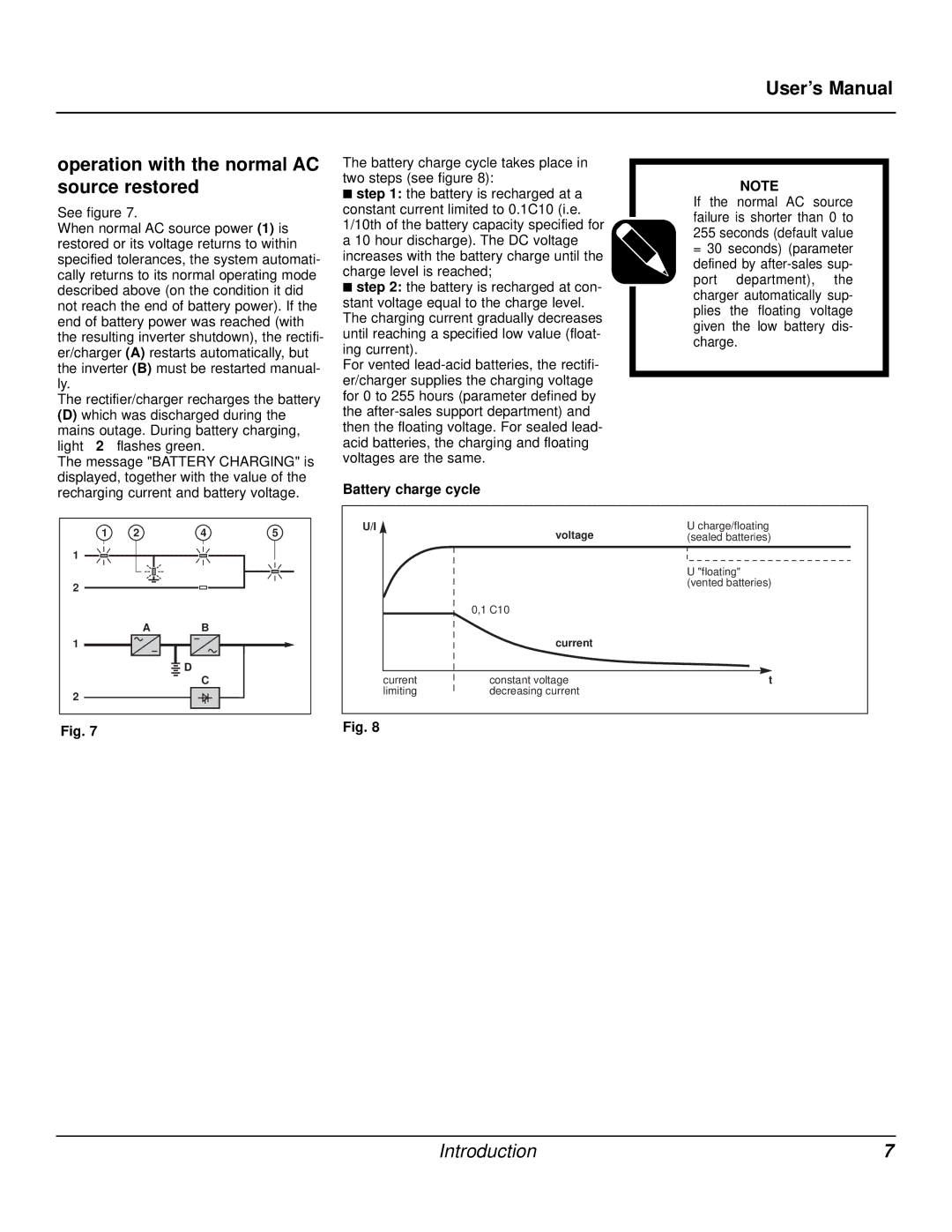
The MGE UPS Systems Galaxy PW is a high-performance uninterruptible power supply designed to provide reliable power protection for critical systems in various environments, including data centers, industrial settings, and commercial facilities. Known for its advanced features and innovative technologies, the Galaxy PW is engineered to ensure seamless operation, even in the event of power disturbances.One of the standout features of the Galaxy PW is its modular design, allowing for easy scalability and flexibility. This design enables users to customize the power capacity according to their specific needs, accommodating future growth without requiring a complete system overhaul. The modular architecture consists of interchangeable power modules that can be easily added or replaced, ensuring minimal downtime and optimized performance.
The Galaxy PW uses cutting-edge double-conversion technology, which provides a high level of power quality and reliability. This technology ensures that any fluctuations in input power do not affect the output, delivering clean and stable electricity to connected equipment. This is particularly essential for sensitive electronics that require a consistent power supply to function correctly.
Another significant characteristic of the Galaxy PW is its energy efficiency. The UPS is designed to operate at high efficiency levels, often exceeding 96%. This not only helps in reducing the overall energy consumption but also lowers operational costs and reduces the carbon footprint of the facility. The Eco-Mode feature allows the UPS to deliver power with minimal energy loss during normal operating conditions.
The Galaxy PW is equipped with advanced communication and management features, including an intuitive graphical LCD display that provides real-time information on the system's status and performance metrics. Users can monitor input and output voltages, current load levels, and battery health at a glance. Additionally, the UPS supports various communication protocols and interfaces, facilitating integration with building management systems and remote monitoring tools.
Safety and reliability are also top priorities for the Galaxy PW. The system features robust battery management to extend the lifespan of the batteries while ensuring optimal performance. The UPS is designed with several protections, including overload, short-circuit, and thermal protection, to safeguard both the UPS and connected loads.
In summary, the MGE UPS Systems Galaxy PW integrates modularity, energy efficiency, advanced monitoring, and robust protection features to deliver unmatched reliability for critical power applications. Its innovative design and technologies make it an ideal choice for businesses seeking a reliable power protection solution.

