5.Link Through

Note: Link Through function only takes effect when switch 4 is set to activated.

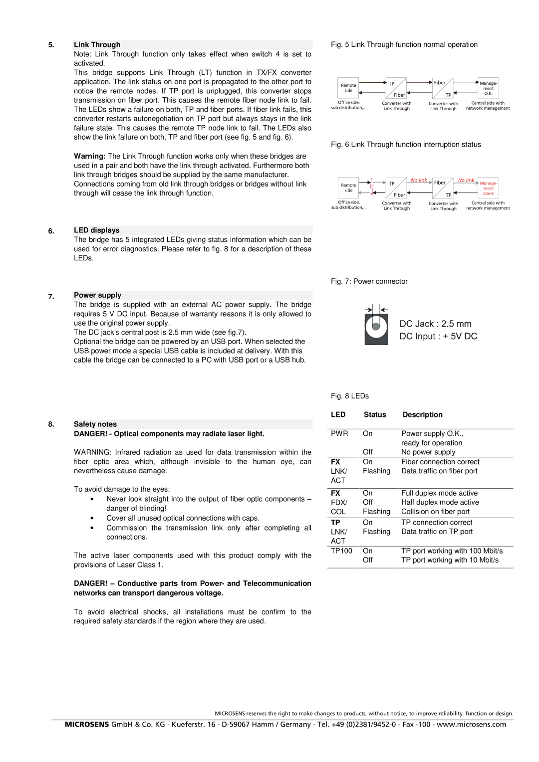
This bridge supports Link Through (LT) function in TX/FX converter application. The link status on one port is propagated to the other port to notice the remote nodes. If TP port is unplugged, this converter stops transmission on fiber port. This causes the remote fiber node link to fail. The LEDs show a failure on both, TP and fiber ports. If fiber link fails, this converter restarts autonegotiation on TP port but always stays in the link failure state. This causes the remote TP node link to fail. The LEDs also show the link failure on both, TP and fiber port (see fig. 5 and fig. 6).

Warning: The Link Through function works only when these bridges are used in a pair and both have the link through activated. Furthermore both link through bridges should be supplied by the same manufacturer.

Connections coming from old link through bridges or bridges without link through will cease the link through function.

6.LED displays

The bridge has 5 integrated LEDs giving status information which can be used for error diagnostics. Please refer to fig. 8 for a description of these LEDs.

7.Power supply

The bridge is supplied with an external AC power supply. The bridge requires 5 V DC input. Because of warranty reasons it is only allowed to use the original power supply.

The DC jack’s central post is 2.5 mm wide (see fig.7).

Optional the bridge can be powered by an USB port. When selected the USB power mode a special USB cable is included at delivery. With this cable the bridge can be connected to a PC with USB port or a USB hub.

8.Safety notes

DANGER! - Optical components may radiate laser light.

WARNING: Infrared radiation as used for data transmission within the fiber optic area which, although invisible to the human eye, can nevertheless cause damage.

To avoid damage to the eyes:

Never look straight into the output of fiber optic components – danger of blinding!

Cover all unused optical connections with caps.

Commission the transmission link only after completing all connections.

The active laser components used with this product comply with the provisions of Laser Class 1.

DANGER! – Conductive parts from Power- and Telecommunication networks can transport dangerous voltage.

To avoid electrical shocks, all installations must be confirm to the required safety standards if the region where they are used.

Fig. 5 Link Through function normal operation

Fig. 6 Link Through function interruption status

Fig. 7: Power connector

Fig. 8 LEDs


LED

Status

Description


PWR

On

Power supply O.K.,


ready for operation


Off

No power supply

FX

On

Fiber connection correct

LNK/

Flashing

Data traffic on fiber port

ACT


FX

On

Full duplex mode active

FDX/

Off

Half duplex mode active

COL

Flashing

Collision on fiber port


TP

On

TP connection correct

LNK/

Flashing

Data traffic on TP port

ACT


TP100

On

TP port working with 100 Mbit/s


Off

TP port working with 10 Mbit/s


MICROSENS reserves the right to make changes to products, without notice, to improve reliability, function or design.

MICROSENS GmbH & Co. KG - Kueferstr. 16 - D-59067 Hamm / Germany - Tel. +49 (0)2381/9452-0 - Fax -100 - www.microsens.com

Page 2
Image 2
Microsens 10/100Base-TX to 100Base-FX manual Link Through, LED displays, Power supply, Safety notes, Status Description

10/100Base-TX to 100Base-FX specifications

Microsens, a leading provider of Ethernet switching and media conversion solutions, offers a highly effective and efficient media converter that bridges the gap between 10/100Base-TX (twisted pair) and 100Base-FX (fiber optic) networks. This essential device is designed for users who require seamless network integration, enhanced performance, and longevity in their infrastructure.

One of the primary features of the Microsens 10/100Base-TX to 100Base-FX media converter is its ability to convert electrical signals from copper cabling to optical signals over fiber. This allows for longer transmission distances, significantly reducing the issues related to attenuation and electromagnetic interference that are commonly experienced in copper-based systems. The 100Base-FX fiber connection enables data transmission distances of up to 2 kilometers when using multimode fiber cables, making it an ideal solution for expansive network environments.

Another key characteristic of the Microsens media converter is its support for both half-duplex and full-duplex operation. This versatility allows organizations to choose the appropriate mode based on their networking needs, whether for compatibility with legacy equipment or for enhanced data throughput in modern applications. The converter also automatically senses the speed of the incoming connection and adjusts accordingly, providing a hassle-free experience during integration.

In terms of technical specifications, the Microsens media converter is designed to be compact and efficient. It typically comes with LED indicators for monitoring power, link status, and data traffic, enabling quick diagnostics and troubleshooting. The converter is housed in a durable metal chassis that ensures longevity and durability, making it suitable for various deployment scenarios, including harsh environments.

Advanced features such as auto-negotiation, extensive network support, and compliance with industry standards further enhance the capabilities of the Microsens solution. The device supports an extensive temperature range, ensuring reliable operation in both indoor and outdoor settings.

Overall, the Microsens 10/100Base-TX to 100Base-FX media converter provides robust performance and reliability, making it a preferred choice for organizations looking to upgrade their networks without incurring significant costs. The combination of practicality, efficiency, and advanced technology positions this media converter as an invaluable tool for modern networking solutions.