PS536GS specifications
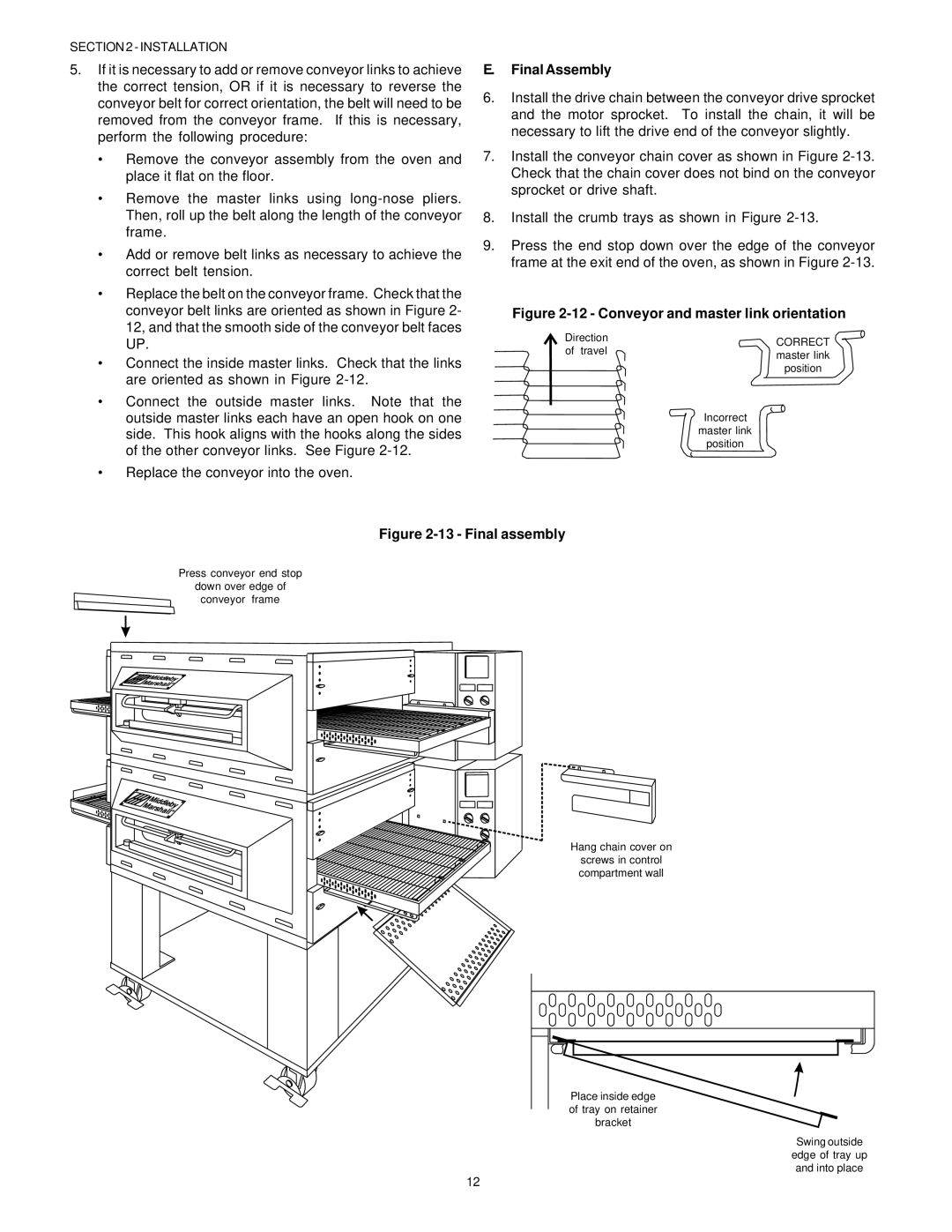
The Middleby Marshall PS536GS is a state-of-the-art commercial conveyor oven designed for high-volume food service operations. Recognized for its unparalleled efficiency and versatility, the PS536GS is ideal for pizza shops, fast-casual dining, and any establishment that demands consistent cooking results with quick service times.One of the most notable features of the PS536GS is its advanced design, which includes a patented jet air technology. This innovation allows for superior heat distribution, ensuring that food is cooked evenly and thoroughly. The oven's variable speed features provide operators with the flexibility to adjust cooking times based on the specific menu items being prepared, making it suitable for baking pizzas, pastries, and a variety of other dishes.
The durable stainless steel construction of the PS536GS not only enhances its longevity but also makes it easy to clean and maintain. The oven is equipped with an advanced digital control panel that allows users to set precise temperatures and monitor cooking progress. This precision is crucial in fast-paced environments where consistency and quality are paramount.
Another standout characteristic of the Middleby Marshall PS536GS is its energy efficiency. The oven is designed to consume less energy while still delivering high performance. This not only reduces operational costs but also aligns with environmentally conscious business practices.
The PS536GS’s innovative design extends to its cooling features as well. The oven’s exterior remains cool to the touch during operation, minimizing the risk of burns and enhancing safety in the kitchen. Furthermore, the oven’s capacity is impressive, accommodating a large volume of food with its spacious conveyor belt system.
Additionally, the Middleby Marshall PS536GS is engineered to support a wide range of menu items, from traditional pizzas to innovative culinary creations. This versatility allows restaurant owners to adapt to changing customer preferences or expand their menus without the need for additional cooking equipment.
In summary, the Middleby Marshall PS536GS is a powerful, efficient, and versatile cooking solution that elevates food service operations. Its combination of advanced technologies, energy efficiency, and user-friendly design makes it an essential oven for any establishment focused on delivering high-quality food quickly and consistently. This exceptional oven not only meets the demands of modern kitchens but also ensures that businesses can thrive in a competitive marketplace.

