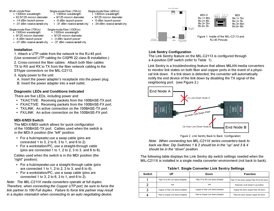
MIL-C2113 specifications
Milan Technology MIL-C2113 is a cutting-edge communication solution designed for military and defense applications, meeting stringent operational requirements in challenging environments. This advanced system combines robust hardware and sophisticated software, providing high levels of reliability and performance essential for modern military operations.One of the main features of the MIL-C2113 is its versatility. It supports multiple communication protocols, making it compatible with various devices and systems in the defense sector. This flexibility allows for seamless integration into existing networks, enhancing interoperability among different equipment used by allied forces. The system can operate across various frequency bands, ensuring effective communication under diverse conditions and terrains.
MIL-C2113 also excels in providing secure communications. It employs advanced encryption technologies that safeguard sensitive data from interception and unauthorized access. The system's capabilities in secure voice, data, and video transmission ensure that military personnel can coordinate effectively without compromising operational security. This is particularly vital in situations where the confidentiality of information can impact mission success.
The ruggedness of the MIL-C2113 is another hallmark characteristic. Built to withstand extreme environmental conditions, the system is designed to operate in harsh terrains, including deserts, jungles, and arctic environments. MIL-SPEC certifications ensure that it meets military standards for temperature, humidity, shock, and vibration, making it reliable in critical situations.
Power efficiency is a key technological advancement in the MIL-C2113. The system features low power consumption without sacrificing performance, allowing for prolonged operational capability without frequent resupply or recharge. This is particularly beneficial for field operations where access to power sources may be limited.
Additionally, the user interface of MIL-C2113 is designed with the end user in mind. Intuitive controls and clear displays enable quick adjustments and easy navigation, allowing military personnel to focus on their mission rather than struggle with complicated technology. The system is also capable of remote monitoring and diagnostics, facilitating proactive maintenance and reducing downtime.
In conclusion, Milan Technology MIL-C2113 is a state-of-the-art communication system tailored for the demanding needs of the military sector. Its combination of versatility, secure communication capabilities, rugged design, energy efficiency, and user-friendly interface makes it an indispensable asset for modern defense operations. As military operations evolve, systems like the MIL-C2113 will play a crucial role in ensuring effective communication and coordination in the field.

