6-5. Troubleshooting Power Source
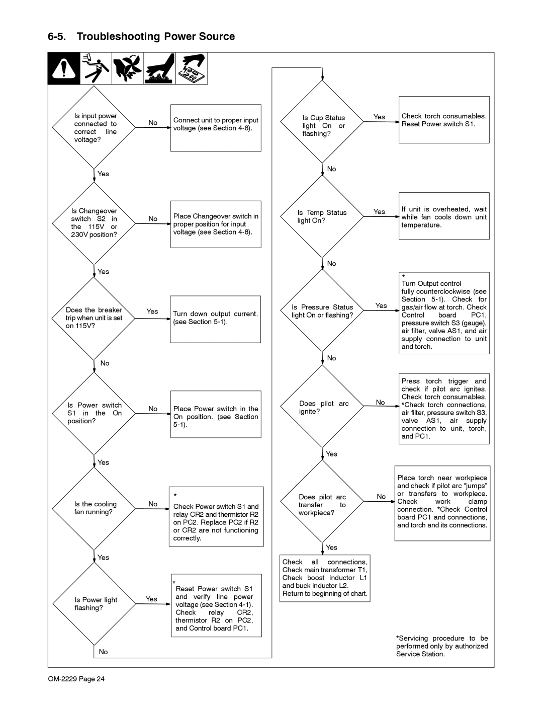
Is input power connected to correct line voltage?
![]() Yes
Yes
Is Changeover switch S2 in the 115V or 230V position?
![]() Yes
Yes
Does the breaker trip when unit is set on 115V?
No
Is Power switch S1 in the On position?
![]() Yes
Yes
Is the cooling fan running?
![]() Yes
Yes
Is Power light flashing?
No
No
No
Yes
No
No
Yes
Connect unit to proper input ![]() voltage (see Section
voltage (see Section
Place Changeover switch in ![]() proper position for input
proper position for input
voltage (see Section
Turn down output current. ![]() (see Section
(see Section
Place Power switch in the ![]() On position. (see Section
On position. (see Section
*
Check Power switch S1 and relay CR2 and thermistor R2 on PC2. Replace PC2 if R2 or CR2 are not functioning correctly.
*Reset Power switch S1 and verify line power ![]() voltage (see Section
voltage (see Section
and Control board PC1.
Is Cup Status light On or flashing?
![]() No
No
Is Temp Status light On?
![]() No
No
Is Pressure Status light On or flashing?
![]() No
No
Does pilot arc ignite?
![]() Yes
Yes
Does pilot arc
transfer to workpiece?
![]() Yes
Yes
Check all connections, Check main transformer T1, Check boost inductor L1 and buck inductor L2.
Return to beginning of chart.
Yes | Check torch consumables. |
| Reset Power switch S1. |
|
|
Yes | If unit is overheated, wait | |
while fan cools down unit | ||
| ||
| temperature. | |
|
|
*
Turn Output control
| fully counterclockwise (see | ||
Yes | Section | ||
gas/air flow at torch. Check | |||
| Control | board | PC1, |
| pressure switch S3 (gauge), | ||
| air filter, valve AS1, and air | ||
| supply | connection | to unit |
and torch.
Press torch trigger and check if pilot arc ignites. Check torch consumables.
No ![]() *Check torch connections, air filter, pressure switch S3, valve AS1, air supply connection to unit, torch, and PC1.
*Check torch connections, air filter, pressure switch S3, valve AS1, air supply connection to unit, torch, and PC1.
Place torch near workpiece and check if pilot arc “jumps” No or transfers to workpiece. ![]() Check work clamp connection. *Check Control board PC1 and connections, and torch and its connections.
Check work clamp connection. *Check Control board PC1 and connections, and torch and its connections.
*Servicing procedure to be performed only by authorized Service Station.