Manuals
/
Miller Electric
/
Power Tools
/
Welder
Miller Electric
812, 652
manual
218 514-B
Models:
652
812
1
35
40
40
Download
40 pages
11.02 Kb
32
33
34
35
36
37
38
39
Troubleshooting
Specifications
Parts list
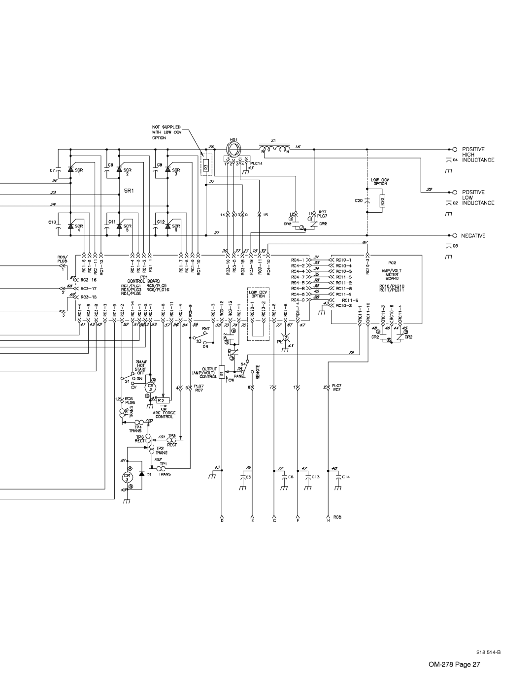
Electrical Diagram
Symbol Usage
Welding Wire can cause injury
Dimension
Maintenance
General Precautionary Label
Safety
Page 35
Image 35
218
514-B
OM-278
Page 27
Page 34
Page 36
Page 35
Image 35
Page 34
Page 36
Contents
File Multi-Process
Processes
Description
From Miller to You
Table of Contents
Decstat6/05
Directives
Standards
HOT Parts can cause severe burns
Symbol Usage
Arc Welding Hazards
Electric Shock can kill
Flying Metal or Dirt can injure eyes
Fumes and Gases can be hazardous
ARC Rays can burn eyes and skin
Welding can cause fire or explosion
Moving Parts can cause injury
Welding Wire can cause injury
Fire or Explosion hazard
Falling Unit can cause injury
About Implanted Medical Devices
Principal Safety Standards
California Proposition 65 Warnings
EMF Information
UNE Décharge Électrique peut entraîner la mort
Symboles utilisés
LE Soudage peut provoquer un in cendie ou une explosion
DES Pièces Chaudes peuvent provoquer des brûlures graves
LES Fumées ET LES GAZ peuvent être dangereux
LA Chute DE L’APPAREIL peut blesser
LE Bruit peut endommager l’ouïe
LES Bouteilles peuvent exploser si elles sont endommagées
Risque D’INCENDIE OU D’EXPLO- Sion
LE Soudage À L’ARC risque de provoquer des interférences
Proposition californienne 65 Avertissements
LES Fils DE Soudage peuvent provoquer des blessures
En ce qui concerne les implants médicaux
Principales normes de sécurité
Information EMF
OM-278
− Definitions
General Precautionary Label
? a
Nameplate Safety Symbols
Input Connection Label
Electric Shock And Airflow Label
Weee Label For Products Sold Within The EU
Manufacturer’s Rating Label For CE Products
Specifications
− Installation
Symbols And Definitions
100% Duty Cycle
CC Mode CV Mode
Duty Cycle And Overheating
Volt-Ampere Curves
460 mm OM-278
Selecting a Location
Movement Location And Airflow
Holes Front
Dimensions And Weights
Dimensions
Weight
Weld Output Terminals
Tipping
VAC Receptacle And Supplementary Protectors
Selecting Cable Sizes
Connecting Weld Output Cables
Gas Flowmeter Regulator
Mig Gmaw Cable Connections
Fcaw Gasless
Turn Off power before making connections
Rear Wire Feeder
Mig Gmaw And Flux Cored Fcaw Cable Connections
Information
To remote On/Off switch
TIG Gtaw Cable Connections
Remote 14 Receptacle RC8 Information
Electrical Service Guide
Connecting Remote Control
Tools Needed Do not overtighten Jumper link nuts
Placing Jumper Links
= GND/PE Earth Ground
Connecting Input Power
Welding Power Source Input Power Con- nections
Disconnect Device Input Power Connec- tions
Controls Non CE Models
− Operation
Controls CE Models
Short Circuit Shutdown
− Maintenance & Troubleshooting
Routine Maintenance
Fuse F1
Trouble Remedy
Troubleshooting
Circuit Diagram
− Electrical Diagram
218 514-B
Recommended Spare Parts
− Parts List
Recommended Spare Parts
Page
Page
Support
Service
Your distributor also gives
Your distributor and/or equipment manufacturer’s
To locate a Distributor or Service Agency visit
Miller Electric Mfg. Co
For assistance in filing or settling claims, contact
Top
Page
Image
Contents