3-2. Outlet Cable, Weld Cable, And Gas Connections
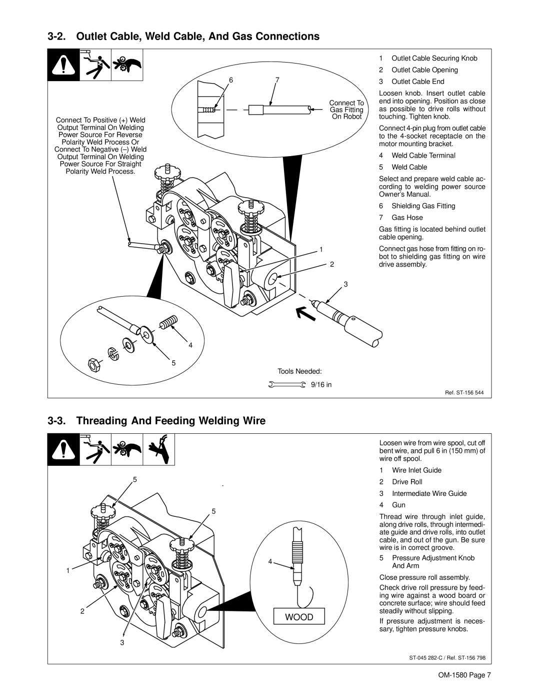
Connect To Positive (+) Weld
Output Terminal On Welding
Power Source For Reverse
Polarity Weld Process Or
Connect To Negative
Output Terminal On Welding
Power Source For Straight
Polarity Weld Process.
67
Connect To
Gas Fitting
On Robot
1
2
3
4
5
Tools Needed:
9/16 in
1Outlet Cable Securing Knob
2Outlet Cable Opening
3Outlet Cable End
Loosen knob. Insert outlet cable end into opening. Position as close as possible to drive rolls without touching. Tighten knob.
Connect
4Weld Cable Terminal
5Weld Cable
Select and prepare weld cable ac- cording to welding power source Owner’s Manual.
6Shielding Gas Fitting
7Gas Hose
Gas fitting is located behind outlet cable opening.
Connect gas hose from fitting on ro- bot to shielding gas fitting on wire drive assembly.
Ref.
3-3. Threading And Feeding Welding Wire
5
5
4
1
2
WOOD
3
Loosen wire from wire spool, cut off bent wire, and pull 6 in (150 mm) of wire off spool.
1Wire Inlet Guide
2Drive Roll
3Intermediate Wire Guide
4Gun
Thread wire through inlet guide, along drive rolls, through intermedi- ate guide and drive rolls, into outlet cable, and out of the gun. Be sure wire is in correct groove.
5Pressure Adjustment Knob And Arm
Close pressure roll assembly.
Check drive roll pressure by feed- ing wire against a wood board or concrete surface; wire should feed steadily without slipping.
If pressure adjustment is neces- sary, tighten pressure knobs.