MOUNTING LOADER
|
| FIG. 3 | |
FIG. 2 | |||
|
| ||
|
|
|
FIG. 1
|
|
|
| FIG. 4B |
|
|
|
|
|
| |
FIG. 4A |
|
| |||||||||
|
|
|
|
|
| FIG. 4C |
|
|
| ||
|
|
|
|
|
|
|
| ||||
|
|
|
|
| |||||||
|
|
|
|
|
|
|
|
|
|
| |
|
|
|
|
|
|
|
|
|
|
| |
|
|
| Upright mast | ||||||||
|
|
|
|
|
|
|
|
| |||
|
|
|
|
|
|
|
|
|
|
|
|
|
| Support shaft |
|
|
|
|
|
|
|
|
|
|
|
|
|
|
|
| Tapered |
|
| ||
|
|
|
|
|
|
|
| Guide Block |
|
| |
|
|
|
|
|
|
|
|
|
|
|
|
FIG. 7
FIG. 5 |
|
|
| Stand Legs |
| Stand Legs Stored |
| FIG. 6 |
|
| |||
|
|
|
|
| ||
|
|
|
|
|
|
|
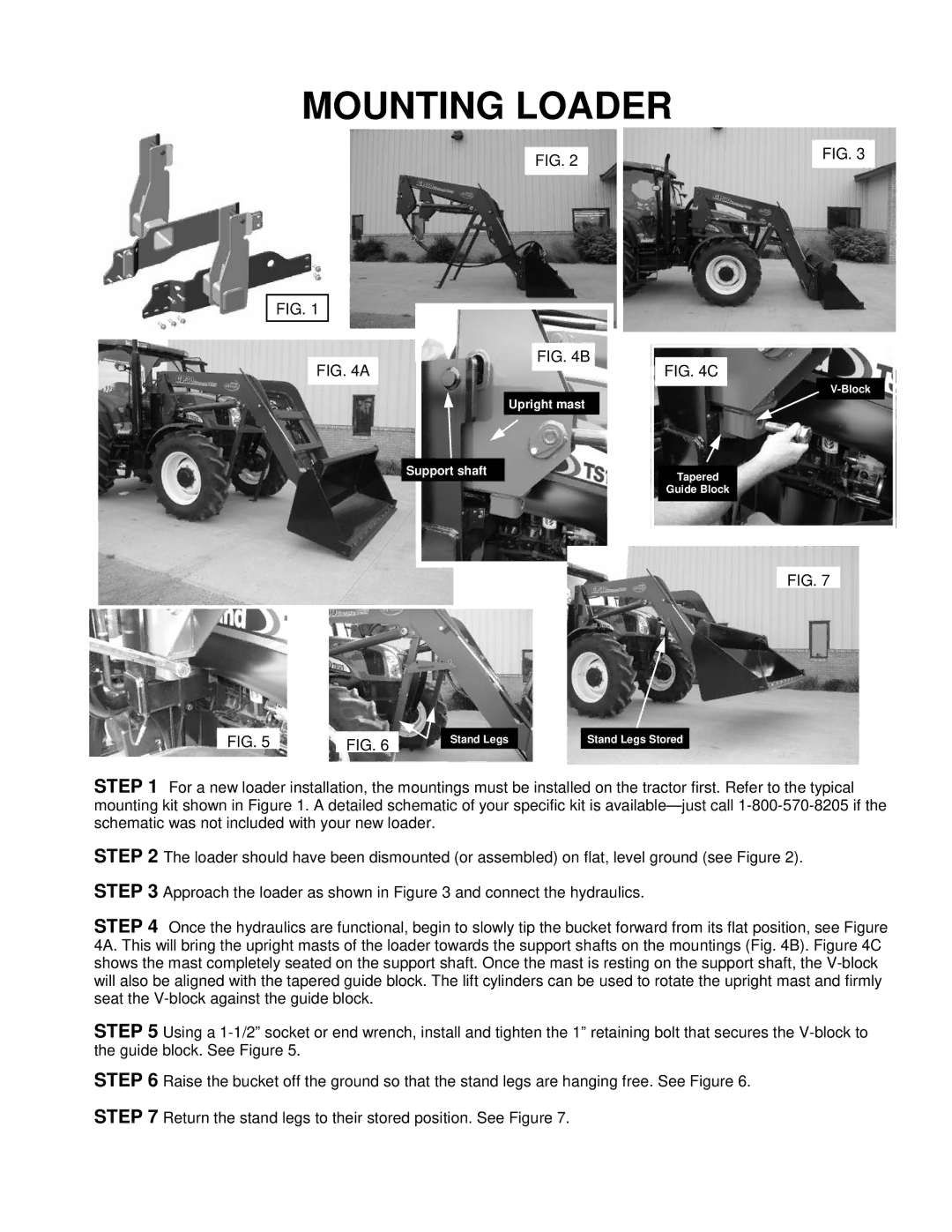
STEP 1 For a new loader installation, the mountings must be installed on the tractor first. Refer to the typical mounting kit shown in Figure 1. A detailed schematic of your specific kit is
STEP 2 The loader should have been dismounted (or assembled) on flat, level ground (see Figure 2).
STEP 3 Approach the loader as shown in Figure 3 and connect the hydraulics.
STEP 4 Once the hydraulics are functional, begin to slowly tip the bucket forward from its flat position, see Figure 4A. This will bring the upright masts of the loader towards the support shafts on the mountings (Fig. 4B). Figure 4C shows the mast completely seated on the support shaft. Once the mast is resting on the support shaft, the
STEP 5 Using a
STEP 6 Raise the bucket off the ground so that the stand legs are hanging free. See Figure 6.
STEP 7 Return the stand legs to their stored position. See Figure 7.
