| SECTION 5 − OPERATION |
|
| |
Controls |
|
|
| |
| 2 | 3 | 6 | 5 |
| 8 |
|
|
|
4 | 7 | 1 | 229 |
|
|
|
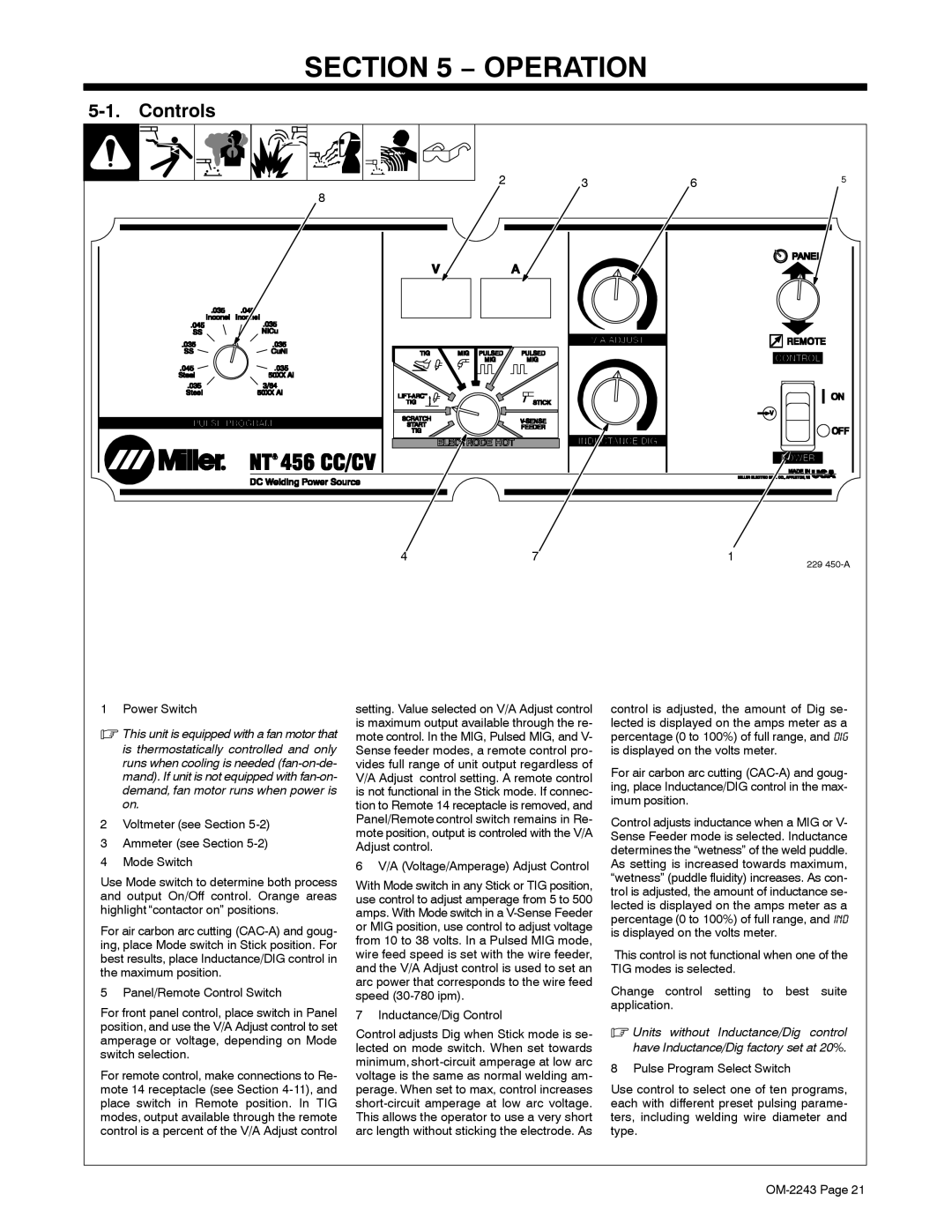
1 Power Switch
.This unit is equipped with a fan motor that
is thermostatically controlled and only runs when cooling is needed
2Voltmeter (see Section 5-2)
3Ammeter (see Section 5-2)
4Mode Switch
Use Mode switch to determine both process and output On/Off control. Orange areas highlight “contactor on” positions.
For air carbon arc cutting
5 Panel/Remote Control Switch
For front panel control, place switch in Panel position, and use the V/A Adjust control to set amperage or voltage, depending on Mode switch selection.
For remote control, make connections to Re- mote 14 receptacle (see Section
setting. Value selected on V/A Adjust control is maximum output available through the re- mote control. In the MIG, Pulsed MIG, and V- Sense feeder modes, a remote control pro- vides full range of unit output regardless of V/A Adjust control setting. A remote control is not functional in the Stick mode. If connec- tion to Remote 14 receptacle is removed, and Panel/Remote control switch remains in Re- mote position, output is controled with the V/A Adjust control.
6 V/A (Voltage/Amperage) Adjust Control
With Mode switch in any Stick or TIG position, use control to adjust amperage from 5 to 500 amps. With Mode switch in a
7 Inductance/Dig Control
Control adjusts Dig when Stick mode is se- lected on mode switch. When set towards minimum,
control is adjusted, the amount of Dig se- lected is displayed on the amps meter as a percentage (0 to 100%) of full range, and dig is displayed on the volts meter.
For air carbon arc cutting
Control adjusts inductance when a MIG or V- Sense Feeder mode is selected. Inductance determines the “wetness” of the weld puddle. As setting is increased towards maximum, “wetness” (puddle fluidity) increases. As con- trol is adjusted, the amount of inductance se- lected is displayed on the amps meter as a percentage (0 to 100%) of full range, and ind is displayed on the volts meter.
This control is not functional when one of the TIG modes is selected.
Change control setting to best suite application.
.Units without Inductance/Dig control have Inductance/Dig factory set at 20%.
8 Pulse Program Select Switch
Use control to select one of ten programs, each with different preset pulsing parame- ters, including welding wire diameter and type.