SECTION 4 − INSTALLATION
4-1. Specifications
Type of | Welding | Wire Feed | Wire Type | Input |
| Max. Wire |
|
| |
Power | Welding | IP | Overall |
| |||||
Input | Speed | And | Spool | Weight | |||||
Source | Circuit | Rating | Dimensions | ||||||
Power | Range | Diameter | Capacity |
| |||||
Type | Rating |
|
|
| |||||
|
|
|
|
|
|
| |||
|
|
|
|
|
|
|
|
| |
|
|
| Solid Steel: |
|
|
|
|
| |
|
|
| .023 − .062 in |
|
|
| Length: |
| |
Constant | 50 − 700 ipm | (0.6 − 1.6 mm); | 330 Amperes |
|
| (397 mm) |
| ||
Voltage (CV) | (1.3 − 18 | Stainless Steel: |
| 14 lb (6.4 kg), | Width: | 25 lb | |||
Arc Voltage, |
| ||||||||
Or Constant | mpm) | .023 − .052 in | At 60% | 23 | |||||
15 − 100 | 8 in (203 mm) | (165 mm) | (11 kg) | ||||||
Current (CC) | Depending On | (0.6 − 1.3 mm); | Duty Cycle |
| |||||
Volts DC |
|
| Height: |
| |||||
DC | Arc Voltage | Flux Cored: |
|
|
|
| |||
|
|
|
|
| |||||
|
|
| .030 − .052 in |
|
|
| (368 mm) |
| |
|
|
| (0.8 − 1.3 mm) |
|
|
|
|
| |
|
|
|
|
|
|
|
|
|
4-2. Gun Recommendation Table
Process | Gun |
|
|
|
|
GMAW − Hard or Corded Wires | M25 Or M40 |
|
|
FCAW − | |
|
|
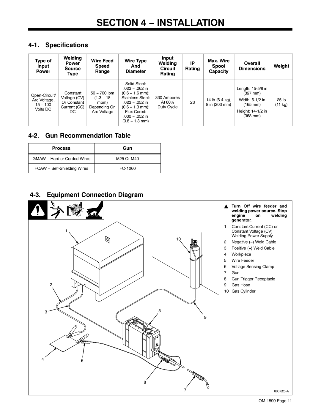
4-3. Equipment Connection Diagram
1
10
| 2 |
3 | 5 |
9
46
8
YTurn Off wire feeder and welding power source. Stop
engine on welding generator.
1Constant Current (CC) or Constant Voltage (CV) Welding Power Supply
2Negative (−) Weld Cable
3Positive (+) Weld Cable
4Workpiece
5Wire Feeder
6Voltage Sensing Clamp
7Gun
8Gun Trigger Receptacle
9Gas Hose
10Gas Cylinder
7 | 803 |