SECTION 5 − OPERATION
5-1. Controls For Non-CE Models
32 1
PURGE TRIGGER POWER
HOLD
8
9
V
4
WIRE
SPEED
(PERCENT)
Front Panel
5 | LO |
|
| 6 CC |
|
|
|
| 7 | ||||||
|
|
|
| ||||||||||||
| |||||||||||||||
|
|
|
|
|
|
|
|
|
|
|
|
|
|
|
|
|
|
|
|
|
|
|
|
|
|
|
|
|
|
|
|
|
|
|
|
|
|
|
|
|
|
|
|
|
|
|
|
|
|
|
|
|
|
|
|
|
|
|
|
|
|
|
|
|
|
|
|
|
|
|
|
|
|
|
|
|
|
|
|
HI | CV |
Internal Control Panel
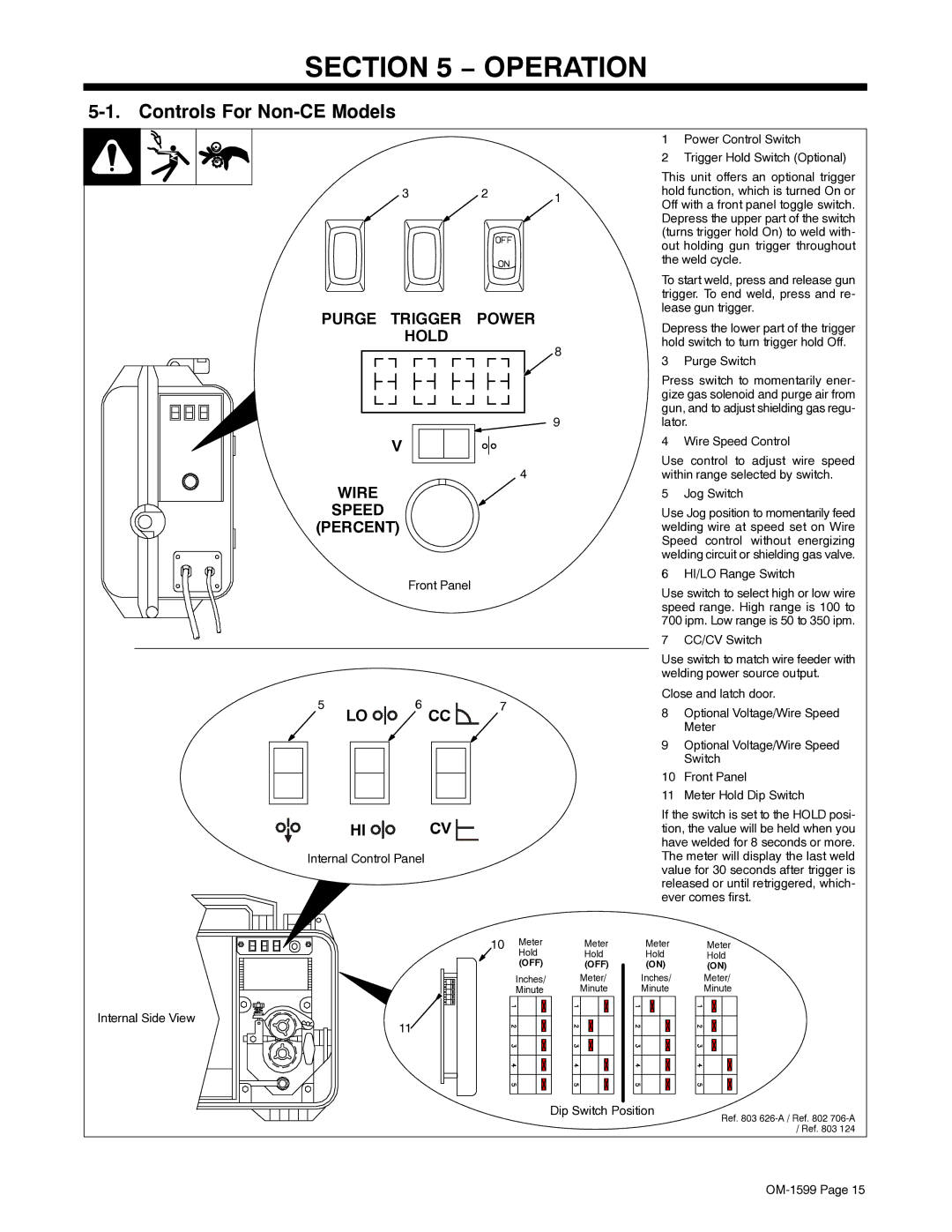
1Power Control Switch
2Trigger Hold Switch (Optional)
This unit offers an optional trigger hold function, which is turned On or Off with a front panel toggle switch. Depress the upper part of the switch (turns trigger hold On) to weld with- out holding gun trigger throughout the weld cycle.
To start weld, press and release gun trigger. To end weld, press and re- lease gun trigger.
Depress the lower part of the trigger hold switch to turn trigger hold Off.
3 Purge Switch
Press switch to momentarily ener- gize gas solenoid and purge air from gun, and to adjust shielding gas regu- lator.
4 Wire Speed Control
Use control to adjust wire speed within range selected by switch.
5 Jog Switch
Use Jog position to momentarily feed welding wire at speed set on Wire Speed control without energizing welding circuit or shielding gas valve.
6 HI/LO Range Switch
Use switch to select high or low wire speed range. High range is 100 to 700 ipm. Low range is 50 to 350 ipm.
7 CC/CV Switch
Use switch to match wire feeder with welding power source output.
Close and latch door.
8Optional Voltage/Wire Speed Meter
9Optional Voltage/Wire Speed Switch
10Front Panel
11Meter Hold Dip Switch
If the switch is set to the HOLD posi- tion, the value will be held when you have welded for 8 seconds or more. The meter will display the last weld value for 30 seconds after trigger is released or until retriggered, which- ever comes first.
Internal Side View
10 | Meter | Meter |
| Hold | Hold |
| (OFF) | (OFF) |
| Inches/ | Meter/ |
| Minute | Minute |
11
Meter Meter
Hold Hold
(ON) (ON)
Inches/ Meter/
Minute Minute
Dip Switch Position
Ref. 803
/ Ref. 803 124
