SECTION 3 – SPECIFICATIONS
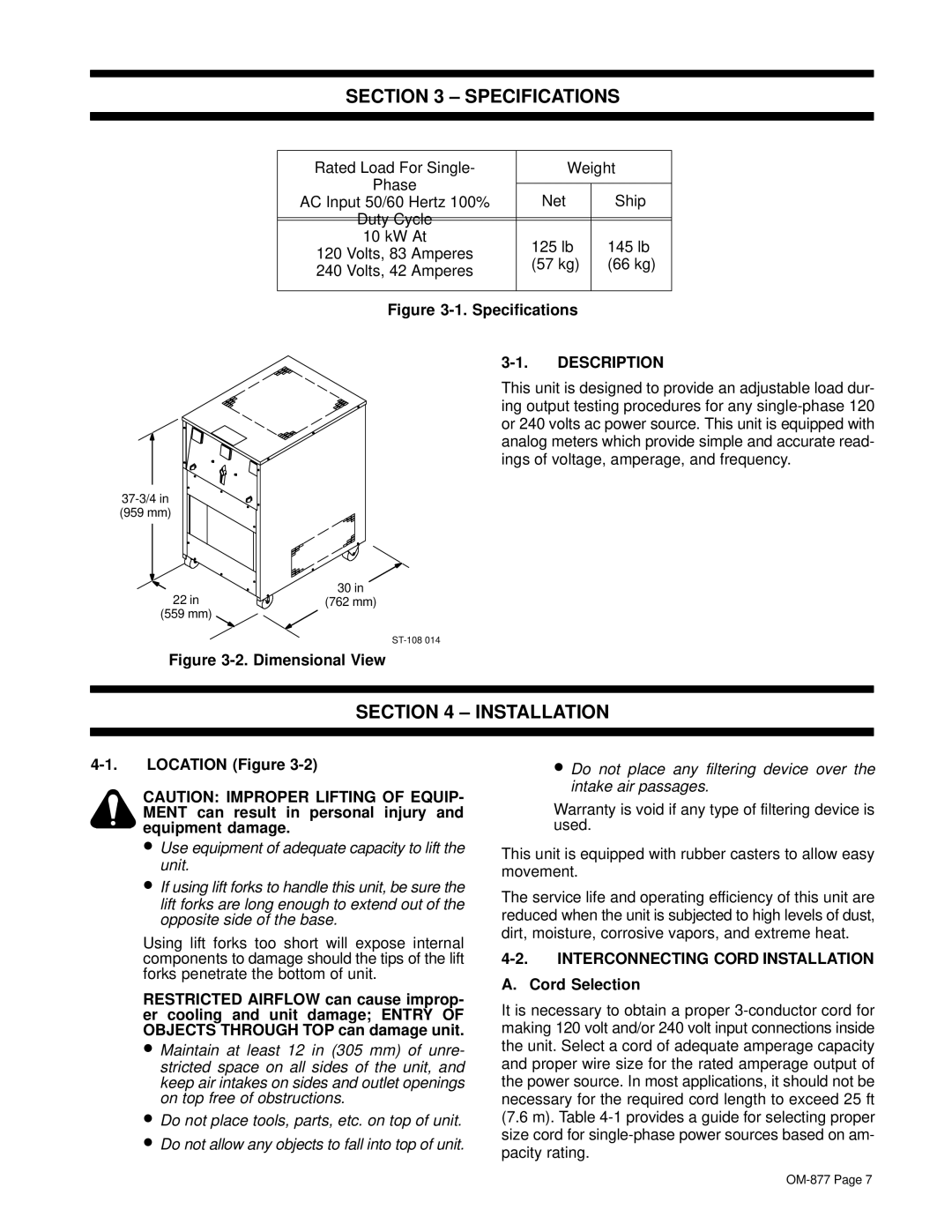
(959 mm)
22 in
(559 mm)
Rated Load For Single- |
| Weight | |
Phase |
|
|
|
| Net | Ship | |
AC Input 50/60 Hertz 100% |
| ||
Duty Cycle |
|
|
|
10 kW At |
| 125 lb | 145 lb |
120 Volts, 83 Amperes |
| ||
| (57 kg) | (66 kg) | |
240 Volts, 42 Amperes |
| ||
|
|
| |
|
|
| |
Figure |
| ||
DESCRIPTION | |||
This unit is designed to provide an adjustable load dur- ing output testing procedures for any
30in
(762 mm)
Figure 3-2. Dimensional View
SECTION 4 – INSTALLATION
LOCATION (Figure |
| • Do not place any filtering device over the | ||
|
| CAUTION: IMPROPER LIFTING OF EQUIP- |
| intake air passages. |
|
|
| Warranty is void if any type of filtering device is | |
|
| MENT can result in personal injury and |
| |
|
| equipment damage. |
| used. |
|
|
| ||
|
| • Use equipment of adequate capacity to lift the | This unit is equipped with rubber casters to allow easy | |
|
| unit. | ||
|
| movement. | ||
|
| • If using lift forks to handle this unit, be sure the | ||
|
| The service life and operating efficiency of this unit are | ||
|
| lift forks are long enough to extend out of the | ||
|
| reduced when the unit is subjected to high levels of dust, | ||
|
| opposite side of the base. | ||
|
| dirt, moisture, corrosive vapors, and extreme heat. | ||
|
| Using lift forks too short will expose internal | ||
|
| INTERCONNECTING CORD INSTALLATION | ||
|
| components to damage should the tips of the lift | ||
|
| forks penetrate the bottom of unit. | A. | Cord Selection |
|
| RESTRICTED AIRFLOW can cause improp- | ||
|
| It is necessary to obtain a proper | ||
|
| er cooling and unit damage; ENTRY OF | ||
|
| OBJECTS THROUGH TOP can damage unit. | making 120 volt and/or 240 volt input connections inside | |
|
| • Maintain at least 12 in (305 mm) of unre- | the unit. Select a cord of adequate amperage capacity | |
|
| stricted space on all sides of the unit, and | and proper wire size for the rated amperage output of | |
|
| keep air intakes on sides and outlet openings | the power source. In most applications, it should not be | |
|
| on top free of obstructions. | necessary for the required cord length to exceed 25 ft | |
|
| • Do not place tools, parts, etc. on top of unit. | (7.6 m). Table | |
• | Do not allow any objects to fall into top of unit. | size cord for | |
pacity rating. | |||
|
|