Table 5-1. Power Requirements For Load
Amperage At Input Voltage
KW | 1 | 1.5 | 2 | 2.5 | 3 | 4 | 5 | 6 | 7 | 7.5 | 8 | 9 | 10 | |
|
|
|
|
|
|
|
|
|
|
|
|
|
| |
AMPERES | 8 | 12 | 17 | 21 | 25 | 33 | 42 | 50 | 58 | 62 | 67 | 75 | 83 | |
AT 120V | ||||||||||||||
|
|
|
|
|
|
|
|
|
|
|
|
| ||
|
|
|
|
|
|
|
|
|
|
|
|
|
| |
AMPERES | 4 | 6 | 8 | 10 | 12 | 17 | 21 | 25 | 29 | 31 | 33 | 37 | 42 | |
AT 240V | ||||||||||||||
|
|
|
|
|
|
|
|
|
|
|
|
| ||
|
|
|
|
|
|
|
|
|
|
|
|
|
|
Power requirements up to 10kw at 120 or 240 vac input for various ampere load values are shown in Table
120 Volt Operation: When this unit is used as a 120 volt load, AMPERAGE load switch settings are added together to obtain the approximate load value. For example, if one switch is set at 20 amperes and the other switch at 20 amperes, the result would be a total load of approximately 40 amperes.
240 Volt Operation: When this unit is used as a 240 volt load, both Amperage load switches must be set at the same value to obtain that approximate load value. For example, if one switch is set at 20 amperes and the other switch at 20 amperes, the result would be a total load of approximately 20 amperes.
IMPORTANT: Do not change either switch setting more than one position higher or lower from the setting on the other switch (see CAUTION at beginning of Section
5-4. VOLTMETER (Figure 5-1)
CAUTION: DC (DIRECT CURRENT) SOURCES will damage unit.
•Do not connect unit to any dc source.
The voltmeter displays the voltage of the ac power source. The scale range is
5-5. HERTZ METER (Figure 5-1)
CAUTION: DC (DIRECT CURRENT) SOURCES will damage unit.
•Do not connect unit to any dc source.
The hertz meter displays the frequency of the power being supplied by the ac power source. The scale range is
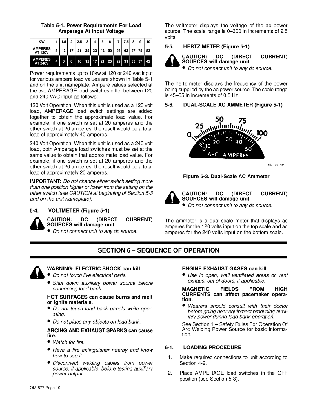
5-6. DUAL-SCALE AC AMMETER (Figure 5-1)
Figure 5-3. Dual-Scale AC Ammeter
CAUTION: DC (DIRECT CURRENT) SOURCES will damage unit.
•Do not connect unit to any dc source.
The ammeter is a
SECTION 6 – SEQUENCE OF OPERATION
WARNING: ELECTRIC SHOCK can kill.
• Do not touch live electrical parts.
•Shut down auxiliary power source before connecting load bank.
HOT SURFACES can cause burns and melt or ignite materials.
•Do not touch load bank panels while oper- ating.
•Do not place any objects on load bank.
ARCING AND EXHAUST SPARKS can cause fire.
•Watch for fire.
•Have a fire extinguisher nearby and know how to use it.
•Disconnect welding cables from power source, if applicable, before testing auxiliary power output.
ENGINE EXHAUST GASES can kill.
•Use in open, well ventilated areas or vent exhaust out of doors, if applicable.
MAGNETIC FIELDS FROM HIGH CURRENTS can affect pacemaker opera- tion.
•Wearers should consult with their doctor before going near equipment producing auxil- iary power during load bank operation.
See Section 1 – Safety Rules For Operation Of Arc Welding Power Source for basic informa- tion.
6-1. LOADING PROCEDURE
1.Make required connections to unit according to Section
2.Place AMPERAGE load switches in the OFF position (see Section