The torque specifications shown here are approxi- mate values.
Torque selector |
|
collar setting | |
1 - 5 | 0 - 17 in. lbs. |
6 - 10 | 21 - 38 in. lbs. |
11 - 15 | 42 - 60 in. lbs. |
16 - 20 | 65 - 85 in. lbs. |
Drill |
|
Low | 600 in. lbs. |
High | 300 in. lbs. |
NOTE: Use a piece of scrap material to test the different clutch positions before driving screws into the workpiece.
Using Control Switch
The control switch may be set to three positions: forward, reverse and lock. Due to a lockout mecha- nism, the control switch can only be adjusted when the ON/OFF switch is not depressed. Always allow the motor to come to a complete stop before using the control switch.
Fig. 5
Push for | Push for |
Forward | Reverse |
PUSH TO CENTE
 R
R
 TO LOCK
For forward (clockwise) rotation, push in the control switch from the right side of the tool. Check the direction of rotation before use.
For reverse (counterclockwise) rotation, push in the control switch from the left side of the tool. Check direction of rotation before use.
To lock the trigger, push the control switch to the center position. The trigger will not work while the control switch is in the center locked position. Always lock the trigger or remove the battery pack before performing maintenance, changing accessories, storing the tool and any time the tool is not in use.
Starting, Stopping and Controlling Speed
1.To start the tool, grasp the handle firmly and pull the trigger.
2.To vary the speed, increase or decrease the pressure on the trigger. The further the trigger is pulled, the greater the speed.
3.To stop the tool, release the trigger. Make sure the bit comes to a complete stop before laying the tool down.
Electric Brake
The electric brake engages when the trigger is released, causing the bit to stop and allowing you to proceed with your work. Generally, the bit stops within two seconds. However, there may be a delay between the time you release the trigger and when the brake engages. Occasionally the brake may miss completely. If the brake misses frequently, the tool needs servicing by an authorized MILWAUKEE service facility.
Drilling
Set both the hammer/drill and torque selector col- lars to the drill positions.
Place the bit on the work surface and apply firm pressure before starting. Too much pressure will slow the bit and reduce drilling efficiency. Too little pressure will cause the bit to slide over the work area and dull the point of the bit.
If the tool begins to stall, reduce pressure slightly to allow the bit to regain speed. If the bit binds, reverse the motor to free the bit from the workpiece.
Drilling in Masonry
When drilling in masonry, select the
Driving Screws and Nut Running
Drill a pilot hole when driving screws into thick or hard materials. Set the torque selector collar to the proper position and set the speed to low. Use the proper style and size screwdriver bit for the type of screw you are using.
With the screwdriver bit in the screw, place the tip of the screw on the workpiece and apply firm pressure before pulling the trigger. Screws can be removed by reversing the motor.
Overloading
Continuous overloading may cause permanent damage to tool or battery pack.
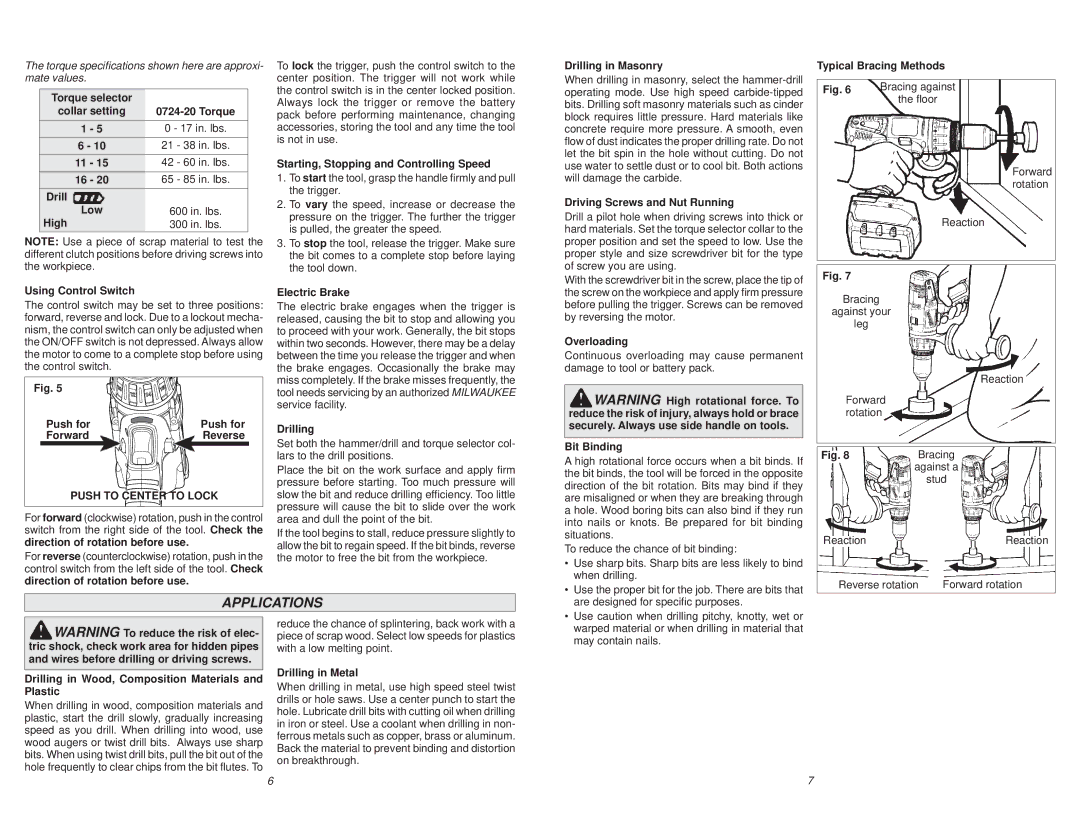
WARNING High rotational force. To reduce the risk of injury, always hold or brace securely. Always use side handle on tools.
Bit Binding
A high rotational force occurs when a bit binds. If the bit binds, the tool will be forced in the opposite direction of the bit rotation. Bits may bind if they are misaligned or when they are breaking through a hole. Wood boring bits can also bind if they run into nails or knots. Be prepared for bit binding situations.
To reduce the chance of bit binding:
• | Use sharp bits. Sharp bits are less likely to bind |
| when drilling. |
• | Use the proper bit for the job. There are bits that |
Typical Bracing Methods
Fig. 6 | Bracing against |
| the floor |
Forward rotation
Reaction
Fig. 7
Bracing
against your
leg
|
|
|
|
|
|
|
|
|
| |||
|
|
|
|
|
|
|
| Reaction | ||||
|
| Forward |
|
|
|
|
|
|
|
| ||
|
|
|
|
|
|
|
|
|
| |||
|
|
|
|
|
|
|
|
| ||||
|
| rotation |
|
|
|
|
|
|
|
| ||
|
|
|
|
|
|
|
|
|
|
|
| |
|
|
|
|
|
|
|
|
|
|
|
|
|
| Fig. 8 |
|
| Bracing | ||||||||
|
|
|
|
| against a | |||||||
|
|
|
|
| ||||||||
|
|
|
|
|
| stud | ||||||
|
|
|
|
|
|
|
|
|
|
|
| |
| Reaction |
| Reaction | |||||||||
|
| Reverse rotation | Forward rotation | |||||||||
APPLICATIONS
are designed for specific purposes. |
• Use caution when drilling pitchy, knotty, wet or |
WARNING To reduce the risk of elec- tric shock, check work area for hidden pipes and wires before drilling or driving screws.
Drilling in Wood, Composition Materials and Plastic
When drilling in wood, composition materials and plastic, start the drill slowly, gradually increasing speed as you drill. When drilling into wood, use wood augers or twist drill bits. Always use sharp bits. When using twist drill bits, pull the bit out of the hole frequently to clear chips from the bit flutes. To
reduce the chance of splintering, back work with a piece of scrap wood. Select low speeds for plastics with a low melting point.
Drilling in Metal
When drilling in metal, use high speed steel twist drills or hole saws. Use a center punch to start the hole. Lubricate drill bits with cutting oil when drilling in iron or steel. Use a coolant when drilling in non- ferrous metals such as copper, brass or aluminum. Back the material to prevent binding and distortion on breakthrough.
warped material or when drilling in material that |
may contain nails. |
6 | 7 |