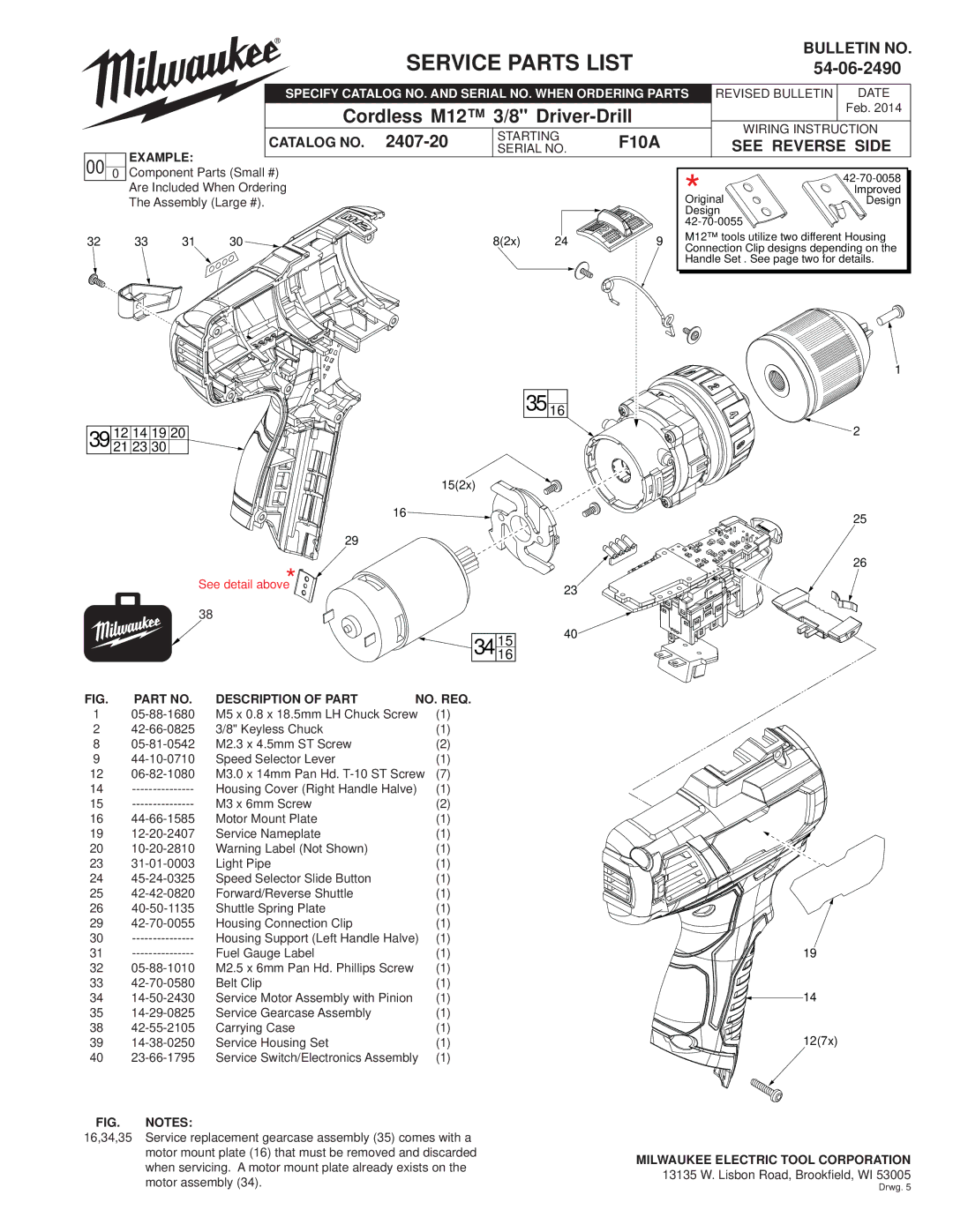
SERVICE PARTS LIST
BULLETIN NO.
|
|
| SPECIFY CATALOG NO. AND SERIAL NO. WHEN ORDERING PARTS | REVISED BULLETIN | DATE | |||||
|
|
| Cordless M12™ 3/8" |
|
| Feb. 2014 | ||||
|
|
|
| WIRING INSTRUCTION | ||||||
|
|
| CATALOG NO. | STARTING | F10A |
| ||||
|
|
|
| SEE REVERSE SIDE | ||||||
00 0 | EXAMPLE: | SERIAL NO. |
| |||||||
|
|
|
| * |
|
| ||||
Component Parts (Small #) |
|
|
|
| ||||||
| Are Included When Ordering |
|
|
|
| Improved | ||||
| The Assembly (Large #). |
|
|
| Original | Design | ||||
|
|
|
|
|
|
| Design |
| ||
|
|
|
|
|
|
|
| |||
32 | 33 | 31 | 30 | 8(2x) | 24 | 9 | M12™ tools utilize two different Housing | |||
Connection Clip designs depending on the | ||||||||||
|
|
|
|
|
|
| ||||
|
|
|
|
|
|
| Handle Set . See page two for details. | |||
1
35 16
39 | 12 14 19 20 |
21 23 30 |
15(2x)
![]() 2
2
16![]()
![]()
![]()
![]()
![]()
![]()
29
See detail above*![]()
![]()
![]()
![]()
![]()
38
![]()
![]() 34 1516
34 1516
25
26
23
40![]()
FIG. | PART NO. | DESCRIPTION OF PART | NO. REQ. | |
1 | M5 x 0.8 x 18.5mm LH Chuck Screw | (1) | ||
2 | 3/8" Keyless Chuck |
| (1) | |
8 | M2.3 x 4.5mm ST Screw |
| (2) | |
9 | Speed Selector Lever |
| (1) | |
12 | M3.0 x 14mm Pan Hd. | (7) | ||
14 | Housing Cover (Right Handle Halve) | (1) | ||
15 | M3 x 6mm Screw |
| (2) | |
16 | Motor Mount Plate |
| (1) | |
19 | Service Nameplate |
| (1) | |
20 | Warning Label (Not Shown) |
| (1) | |
23 | Light Pipe |
| (1) | |
24 | Speed Selector Slide Button |
| (1) | |
25 | Forward/Reverse Shuttle |
| (1) | |
26 | Shuttle Spring Plate |
| (1) | |
29 | Housing Connection Clip |
| (1) | |
30 | Housing Support (Left Handle Halve) | (1) | ||
31 | Fuel Gauge Label |
| (1) | |
32 | M2.5 x 6mm Pan Hd. Phillips Screw |
| (1) | |
33 | Belt Clip |
| (1) | |
34 | Service Motor Assembly with Pinion |
| (1) | |
35 | Service Gearcase Assembly |
| (1) | |
38 | Carrying Case |
| (1) | |
39 | Service Housing Set |
| (1) | |
40 | Service Switch/Electronics Assembly | (1) | ||
FIG. NOTES:
16,34,35 Service replacement gearcase assembly (35) comes with a motor mount plate (16) that must be removed and discarded when servicing. A motor mount plate already exists on the motor assembly (34).
19
14
12(7x)
MILWAUKEE ELECTRIC TOOL CORPORATION
13135 W. Lisbon Road, Brookfield, WI 53005
Drwg. 5
