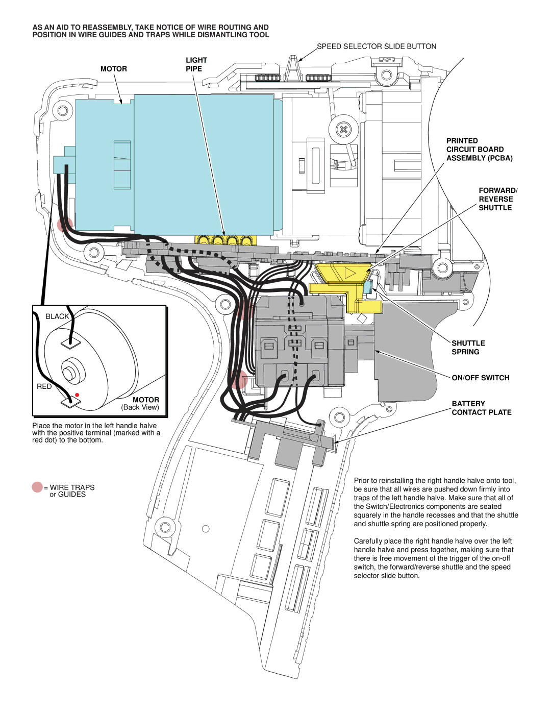
AS AN AID TO REASSEMBLY, TAKE NOTICE OF WIRE ROUTING AND
POSITION IN WIRE GUIDES AND TRAPS WHILE DISMANTLING TOOL
SPEED SELECTOR SLIDE BUTTON
LIGHT
MOTORPIPE
PRINTED
CIRCUIT BOARD
ASSEMBLY (PCBA)
FORWARD/
REVERSE
SHUTTLE
BLACK |
RED |
MOTOR |
(Back View) |
Place the motor in the left handle halve with the positive terminal (marked with a red dot) to the bottom.
= WIRE TRAPS or GUIDES
SHUTTLE
SPRING
ON/OFF SWITCH
BATTERY
CONTACT PLATE
Prior to reinstalling the right handle halve onto tool, be sure that all wires are pushed down firmly into traps of the left handle halve. Make sure that all of the Switch/Electronics components are seated squarely in the handle recesses and that the shuttle and shuttle spring are positioned properly.
Carefully place the right handle halve over the left handle halve and press together, making sure that there is free movement of the trigger of the
