propel the tool in direction opposite to the wheel’s movement at the point of snagging.
•Use special care when working corners, sharp edges etc. Avoid bouncing and snagging the ac- cessory. Corners, sharp edges or bouncing have a tendency to snag the rotating accessory and cause loss of control or kickback.
•Do not attach a saw chain woodcarving blade or toothed saw blade. Such blades create frequent kickback and loss of control.
Safety Warnings Specific for Sanding Operations:
•Do not use excessively oversized sanding disc paper. Follow manufacturers recommendations, when selecting sanding paper. Larger sanding paper extending beyond the sanding pad presents a laceration hazard and may cause snagging, tearing of the disc or kickback.
Safety Warnings Specific for Polishing Operations:
•Do not allow any loose portion of the polishing bonnet or its attachment strings to spin freely. Tuck away or trim any loose attachment strings. Loose and spinning attachment strings can entangle your fingers or snag on the workpiece.
Additional Safety Warnings
•Maintain labels and nameplates. These carry im- portant information. If unreadable or missing, contact a MILWAUKEE service facility for a free replacement.
•WARNING: Some dust created by power sanding, sawing, grinding, drilling, and other construction ac- tivities contains chemicals known to cause cancer, birth defects or other reproductive harm.
Some examples of these chemicals are:
•lead from
•crystalline silica from bricks and cement and other masonry products, and
•arsenic and chromium from
Your risk from these exposures varies, depending on how often you do this type of work. To reduce your exposure to these chemicals: work in a well ventilat- ed area, and work with approved safety equipment, such as those dust masks that are specially designed to filter out microscopic particles.
OPERATION
![]() WARNING Always remove battery pack before changing or removing acces- sories. Only use accessories specifically recommended for this tool. Others may be hazardous.
WARNING Always remove battery pack before changing or removing acces- sories. Only use accessories specifically recommended for this tool. Others may be hazardous.
![]()
![]() WARNING To reduce the risk of injury, wearsafetygogglesorglasseswithsideshields.
WARNING To reduce the risk of injury, wearsafetygogglesorglasseswithsideshields.
Fuel Gauge
To determine the amount of charge left in the bat- tery, pull the trigger. The Fuel Gauge will light up for
To signal the end of charge, 1 light on the fuel gauge will flash for
Selecting Speed
The speed selector is on top of the ![]()
![]()
![]() motor housing. Allow the tool to come
motor housing. Allow the tool to come ![]()
![]()
![]() to a complete stop before changing
to a complete stop before changing ![]()
![]()
![]()
![]()
![]()
![]()
![]()
![]()
![]() speeds.
speeds.![]()
![]()
![]()
![]()
![]()
![]()
![]()
![]()
![]()
![]()
Sanding Disc Selection
Use sanding discs and accessories that are:
•correct size as written on tool’s nameplate.
•rated at or above the RPM listed on the tool’s nameplate.
•correct accessory, wheel type and grit for the job. Refer to the table below to select the correct type of sanding disc for your job. Generally, use 24 or 36 grit for heavy stock removal; 50, 60, or 80 grit for medium stock removal and 120 grit for finishing. Always begin with a coarse grit, using successively finer grits to obtain the desired finish. See your MILWAUKEE Electric Tool Catalog for a complete list of sanding discs.
Aluminum Oxide
For fast cutting, general purpose discs for most metal jobs. Best for
Aluminum Zirconia Bi-Cut
Unique grit pattern is arranged in clusters for fast- er stock removal and cleaning. Ideal for removing paint from cars, boats, etc. without clogging.
SPECIFICATIONS
Cat. No. | Volts DC | No Load RPM | Spindle |
| Sanding Disc | Polishing Pad |
|
Thread Size |
| Diameter | Diameter |
| |||
12 | High 0 - 8 300 | M9 x 0.75 |
| 2" | 3" |
| |
|
| Low 0 - 2 800 |
|
|
|
|
|
|
|
|
|
|
|
| |
|
| SYMBOLOGY |
|
|
|
| |
|
|
|
|
|
| ||
| Volts |
|
|
| No Load Revolutions per Minute | ||
|
|
|
| (RPM) |
|
| |
|
|
|
|
|
|
| |
|
|
|
|
|
| ||
| Direct Current |
|
| Underwriters Laboratories, Inc. | |||
| C | US United States and Canada | |||||
1. For Low speed, push the speed selector to display “1”.
2. For High speed, push the speed selector to display “2”.
Locking the Trigger
Always allow the motor to come to a complete stop before locking the trigger. Always lock the trigger or remove the battery pack before performing
maintenance, changing |
accessories, storing the |
tool and any time the tool |
is not in use. |
To lock the trigger, push |
the trigger lock from the |
Ceramic
Lasts up to 3 times longer than Aluminum Ox- ide Discs. For general metal working. Ideal for tough jobs.
Installing/Removing Sanding Discs
Use Roloc™ type sanding discs.
1.Remove the battery pack.
2.Press in the spindle lock and thread sanding disc onto the backing pad. Hand tighten securely.
3.To remove, reverse the procedure.
MAINTENANCE
FUNCTIONAL DESCRIPTION
|
|
| 5 | 6 | 7 |
| 4 |
|
|
|
|
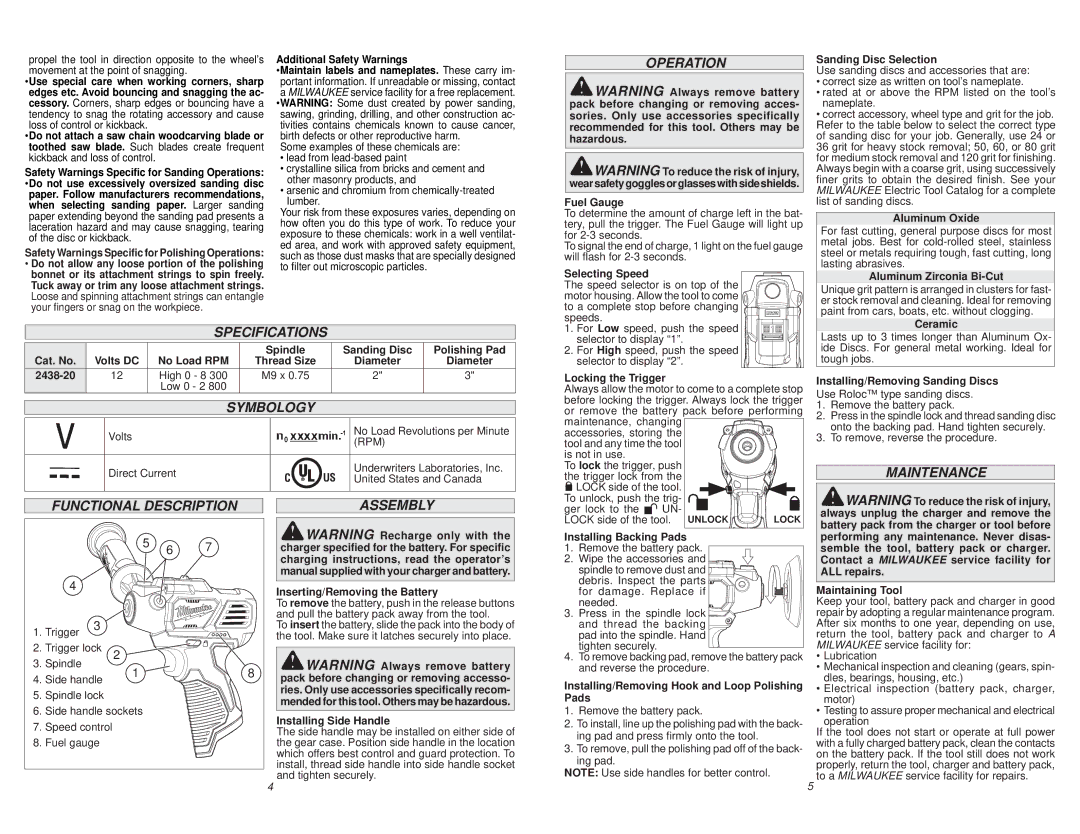
1. | Trigger | 3 |
|
|
|
|
|
|
| ||
2. | Trigger lock | 2 |
|
| |
3. | Spindle |
| 1 |
| 8 |
4. | Side handle |
| |||
|
|
| |||
5. | Spindle lock |
|
|
| |
6. | Side handle sockets |
|
| ||
7. | Speed control |
|
|
| |
8. | Fuel gauge |
|
|
| |
ASSEMBLY
![]() WARNING Recharge only with the charger specified for the battery. For specific charging instructions, read the operator’s manual supplied with your charger and battery.
WARNING Recharge only with the charger specified for the battery. For specific charging instructions, read the operator’s manual supplied with your charger and battery.
Inserting/Removing the Battery
To remove the battery, push in the release buttons and pull the battery pack away from the tool.
To insert the battery, slide the pack into the body of the tool. Make sure it latches securely into place.
![]() WARNING Always remove battery pack before changing or removing accesso- ries. Only use accessories specifically recom- mended for this tool. Others may be hazardous.
WARNING Always remove battery pack before changing or removing accesso- ries. Only use accessories specifically recom- mended for this tool. Others may be hazardous.
Installing Side Handle
The side handle may be installed on either side of the gear case. Position side handle in the location which offers best control and guard protection. To install, thread side handle into side handle socket and tighten securely.
LOCK side of the tool. |
|
| |
To unlock, push the trig- | . |
| |
ger lock to the | UN- |
| |
LOCK side of the tool. | UNLOCK | LOCK | |
Installing Backing Pads |
|
| |
1. Remove the battery pack. |
| ||
2. Wipe the accessories and |
| ||
spindle to remove dust and |
| ||
debris. Inspect the parts |
| ||
for damage. Replace if |
| ||
needed. |
|
|
|
3. Press in the spindle lock |
| ||
and thread the backing |
| ||
pad into the spindle. Hand |
| ||
tighten securely. |
|
|
|
4.To remove backing pad, remove the battery pack and reverse the procedure.
Installing/Removing Hook and Loop Polishing Pads
1.Remove the battery pack.
2.To install, line up the polishing pad with the back- ing pad and press firmly onto the tool.
3.To remove, pull the polishing pad off of the back-
ing pad.
NOTE: Use side handles for better control.
![]() WARNING To reduce the risk of injury, always unplug the charger and remove the battery pack from the charger or tool before performing any maintenance. Never disas- semble the tool, battery pack or charger. Contact a MILWAUKEE service facility for ALL repairs.
WARNING To reduce the risk of injury, always unplug the charger and remove the battery pack from the charger or tool before performing any maintenance. Never disas- semble the tool, battery pack or charger. Contact a MILWAUKEE service facility for ALL repairs.
Maintaining Tool
Keep your tool, battery pack and charger in good repair by adopting a regular maintenance program. After six months to one year, depending on use, return the tool, battery pack and charger to A MILWAUKEE service facility for:
•Lubrication
•Mechanical inspection and cleaning (gears, spin- dles, bearings, housing, etc.)
•Electrical inspection (battery pack, charger, motor)
•Testing to assure proper mechanical and electrical operation
If the tool does not start or operate at full power with a fully charged battery pack, clean the contacts on the battery pack. If the tool still does not work properly, return the tool, charger and battery pack, to a MILWAUKEE service facility for repairs.
4 | 5 |