in the groove, and can kickback. When a cut- off wheel grabs, the wheel itself usually breaks. When the steel saw, high-speed cutters or tung- sten carbide cutter grab, it may jump from the groove and you could lose control of the tool.
•Do not position your hand in line with and behind the rotating wheel. When the wheel, at the point of operation, is moving away from your hand, the possible kickback may propel the spin- ning wheel and the power tool directly at you.
•Allow brushes to run at operating speed for at least one minute before using them. During this time no one is to stand in front or in line with the brush. Loose bristles or wires will be discharged during the run-in time.
•Direct the discharge of the spinning wire brush away from you. Small particles and tiny wire fragments may be discharged at high veloc- ity during the use of these brushes and may be- come imbedded in your skin.
•Maintain labels and nameplates. These carry important information. If unreadable or missing, contact a MILWAUKEE service facility for a free replacement.
•WARNING: Some dust created by power sand- ing, sawing, grinding, drilling, and other construc- tion activities contains chemicals known to cause cancer, birth defects or other reproductive harm. Some examples of these chemicals are:
•lead from lead-based paint
•crystalline silica from bricks and cement and other masonry products, and
•arsenic and chromium from chemically-treated lumber.
Your risk from these exposures varies, depending on how often you do this type of work. To reduce your exposure to these chemicals: work in a well ventilated area, and work with approved safety equipment, such as those dust masks that are spe- cially designed to filter out microscopic particles.
SPECIFICATIONS
Max.
VoltsAccessory Cat. No. DC No load RPM Collet Diameter
2460-2012 5000 - 32000 1/8" * | 2" |
* accepts standard collet sizes 1/32", 1/16", 3/32", 1/8"
SYMBOLOGY
Volts
Direct Current
No Load Revolutions per
Minute (RPM)
Underwriters Laboratories, Inc.
United States and Canada
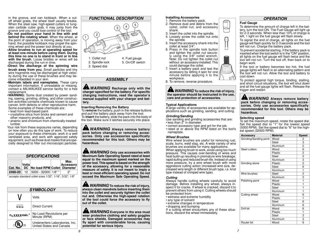
FUNCTIONAL DESCRIPTION
| | 3 | 4 | 5 |
| | |
| | | |
1 | 2 | | | |
| | | |
1. | Collet nut | 4. | Fuel gauge |
2. | Spindle lock | 5. | On/Off switch |
3. | Speed dial | | | |
ASSEMBLY
 WARNING Recharge only with the charger specified for the battery. For specific charging instructions, read the operator’s manual supplied with your charger and bat- tery.
Inserting/Removing the Battery
To remove the battery, push in the release buttons and pull the battery pack away from the tool.
To insert the battery, slide the pack into the body of the tool. Make sure it latches securely into place.
 WARNING Always remove battery pack before changing or removing acces- sories. Only use accessories specifically recommended for this tool. Others may be hazardous.
 WARNING Only use accessories with Maximum Safe Operating Speed rated at least equal to the maximum speed marked on the power tool. This speed is based on the strength of the accessory, allowing for a reasonable measure of safety. It is not meant to imply a best or most efficient operating speed. Do not exceed the Maximum Safe Operating Speed.
 WARNING To reduce the risk of injury, always clean mandrels before inserting them into the collet and securely tighten the collet nut and. Otherwise the high-speed rotation of the tool could force the accessory to fly out of the collet.
 WARNING Everyone in the area must wear protective clothing and safety goggles or face shields. Damaged accessories may fly apart with considerable force, causing potential for serious injury.
Installing Accessories
1.Remove the battery pack.
2.Remove dust and debris from the collet, collet nut, and accessory shank.
3.Insert the collet into the spindle.
4.Loosely screw the collet nut onto the spindle.
5.Insert the accessory shank into the collet at least 3/4".
6.Press in the spindle lock button and tighten the collet nut secure-
ly using the 3/8" collet wrench. Note: Do not tighten the collet nut without an accessory installed. This could damage the collet.
7.Insert a battery pack and test the 


 accessory by letting it spin for one


 minute before applying it to the
  workpiece.
8.To remove, reverse procedure.
 WARNING To reduce the risk of injury, the operator should be instructed in the use, care and protection of accessories.
Typical Applications
A large variety of accessories are available for ap- plications such as grinding, sanding, and cutting.
Grinding/Sanding
Use sanding and grinding accessories that are:
•less than 2" in diameter.
•correct accessory type and grit for the job.
•rated at or above the RPM listed on the tool's nameplate.
Wheel Brushes
Wire wheel brushes are useful for removing rust, scale, burrs, weld slag, etc. A wide variety of wire brushes are available for many applications.
When applying brush to work, avoid using too much pressure. This causes over-bending of wires and heat build-up resulting in premature wire breakage, rapid dulling and reduced brush life. Instead of using more pressure, try a wire wheel brush with more aggressive cutting action (increased wire size, de- creased wire length or different brush type, i.e. knot type instead of crimped wire type).
Cutting
Always handle cutting wheels carefully to avoid damage. Before installing any wheel, always in- spect it for cracks. If wheel is cracked, discard it to prevent others from using it. Cutting wheels should be protected from:
•wetness and extreme humidity
•any type of solvent
•extreme changes in temperature
•dropping and bumping
If a cutting wheel encounters any of these situa- tions, discard the wheel immediately.
OPERATION
Fuel Gauge
To determine the amount of charge left in the bat- tery, turn the tool ON. The Fuel Gauge will light up for 2-3 seconds. When less than 10% of charge is left, 1 light on the fuel gauge will flash slowly.
To signal the end of charge, all lights on the fuel gauge will flash quickly for 2-3 seconds and the tool will not run. Charge the battery pack.
To prevent accidental starting, if the battery pack is inserted when the tool switch is in the "ON" position, all lights on the fuel gauge will flash twice and the tool will not run. Turn the tool off, then back on to begin work.
If the tool or battery becomes too hot, the fuel gauge lights will flash in an alternating pattern and the tool will not run. Allow the tool and battery to cool down.
To protect against high torque, binding, stalling, and short circuit situations, the tool will shut down and all the fuel gauge lights will flash. Release the trigger and restart.
 WARNING Always remove battery pack before changing or removing acces- sories. Only use accessories specifically recommended for this tool. Others may be hazardous.
Selecting speed
To set the maximum speed, rotate the speed dial. Set the speed dial to "1" for the lowest speed (5000 RPM). Set the speed dial to "6" for the high- est speed (32000 RPM).
Accessory | Material | Speed |
Grinding/Sanding point | Wood | 2 |
| Steel | 3 |
| Aluminum | 2 |
Steel cutters | Wood | 6 |
| Plastic | 2 |
| Steel | 2 |
| Aluminum | 3 |
Grinding stone | Plastic | 2 |
| Steel | 6 |
| Aluminum | 1 |
Wire brushes | Steel | 2 |
| Aluminum | 2 |
Polishing point | Wood | 1 |
| Plastic | 1 |
| Steel | 1 |
| Aluminum | 1 |
Cutting wheel | Wood | 6 |
| Plastic | 1 |
| Steel | 6 |
| Aluminum | 6 |
Drill bit | Wood | 6 |
| Plastic | 1 |
| Steel | 3 |
| Aluminum | 3 |
Router bit | Wood | 6 |