EXTENSION CORDS
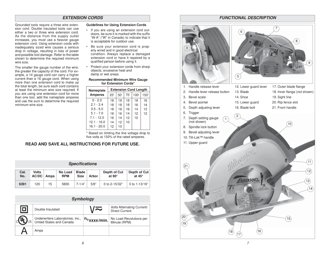
FUNCTIONAL DESCRIPTION
Grounded tools require a three wire exten- sion cord. Double insulated tools can use either a two or three wire extension cord. As the distance from the supply outlet increases, you must use a heavier gauge extension cord. Using extension cords with inadequately sized wire causes a serious drop in voltage, resulting in loss of power and possible tool damage. Refer to the table shown to determine the required minimum wire size.
The smaller the gauge number of the wire, the greater the capacity of the cord. For ex- ample, a 14 gauge cord can carry a higher current than a 16 gauge cord. When using more than one extension cord to make up the total length, be sure each cord contains at least the minimum wire size required. If you are using one extension cord for more than one tool, add the nameplate amperes and use the sum to determine the required minimum wire size.
Guidelines for Using Extension Cords
•If you are using an extension cord out- doors, be sure it is marked with the suffix
•Be sure your extension cord is prop- erly wired and in good electrical condition. Always replace a damaged extension cord or have it repaired by a qualified person before using it.
•Protect your extension cords from sharp objects, excessive heat and
damp or wet areas.
Recommended Minimum Wire Gauge
for Extension Cords*
Nameplate | Extension Cord Length | |||||
Amperes | 25' | 50' | 75' | 100' | 150' | |
|
|
|
|
|
| |
0 - 2.0 | 18 | 18 | 18 | 18 | 16 | |
2.1 | - 3.4 | 18 | 18 | 18 | 16 | 14 |
3.5 | - 5.0 | 18 | 18 | 16 | 14 | 12 |
5.1 | - 7.0 | 18 | 16 | 14 | 12 | 12 |
7.1 - 12.0 | 16 | 14 | 12 | 10 |
| |
12.1 | - 16.0 | 14 | 12 | 10 |
|
|
16.1 | - 20.0 | 12 | 10 |
|
|
|
|
|
|
|
|
|
|
*Based on limiting the line voltage drop to five volts at 150% of the rated amperes.
4
3
1.Handle release lever
2.Handle lever release button
3.Bevel scale
4.Bevel pointer
5.Depth adjusting lever
6.Trigger
7. Depth setting gauge | 1 |
(not shown) |
|
8. | Spindle lock button |
9. | Bevel adjusting lever |
10. | |
7
6
8
|
| 9 |
5 |
|
|
12. Lower guard lever | 17. Outer blade flange | |
13. Blade | 18. Inner flange (not shown) | |
14. Shoe | 19. | Sight line |
15. Lower guard | 20. | Rip fence slot |
16. Blade bolt | 21. Front handle | |
2 |
|
|
|
| 10 |
READ AND SAVE ALL INSTRUCTIONS FOR FUTURE USE.
Specifications
Cat. | Volts |
| No Load | Blade |
| Depth of Cut | Depth of Cut |
No. | AC/DC | Amps | RPM | Size | Arbor | at 90° | at 45° |
|
|
|
|
|
|
|
|
6391 | 120 | 15 | 5800 | 5/8” | 0 to | 0 to | |
|
|
|
|
|
|
|
|
Symbology
| Double Insulated |
|
| Volts Alternating Current/ |
|
|
| Direct Current | |
|
|
|
| |
|
|
|
|
|
| Underwriters Laboratories, Inc., |
|
| No Load Revolutions per |
| United States and Canada |
|
| Minute (RPM) |
|
|
|
|
|
| Amps |
|
|
|
|
|
|
|
|
|
| 6 |
| |
11. Upper guard |
![]() 11
11
21
12
13
14
20 | 15 |
| |
19 |
|
1816
17
7