TOOL ASSEMBLY
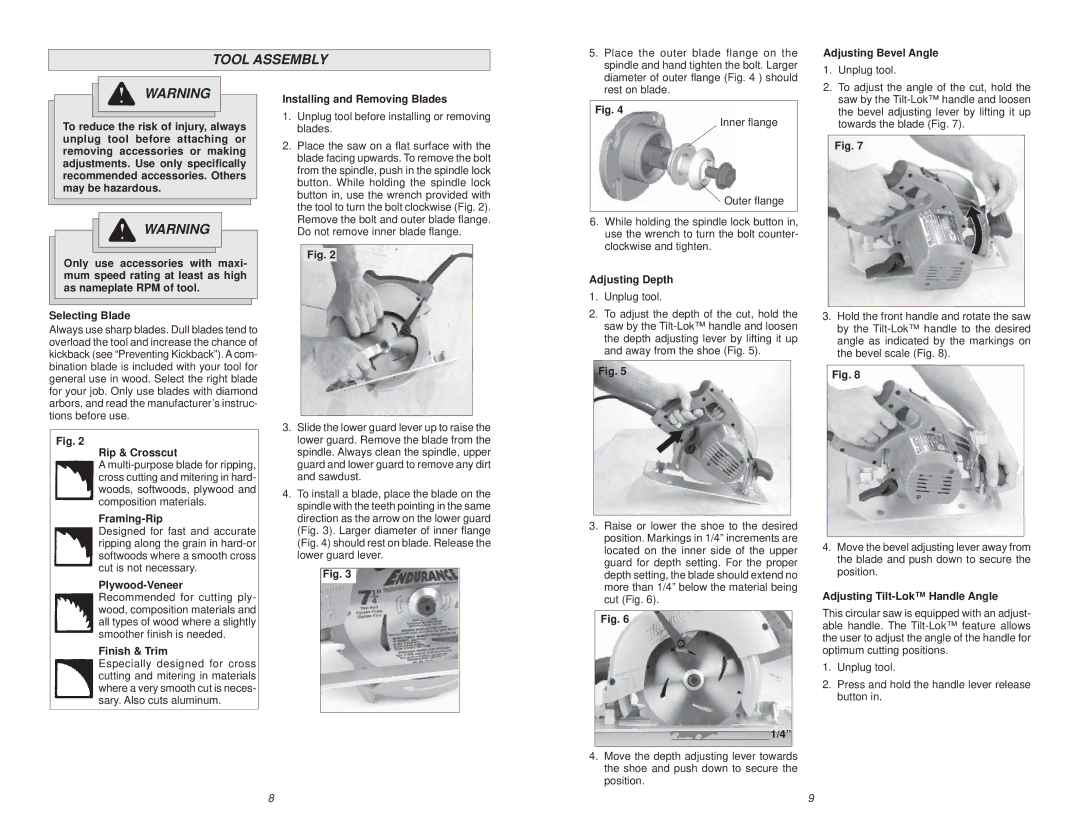
5. Place the outer blade flange on the |
spindle and hand tighten the bolt. Larger |
diameter of outer flange (Fig. 4 ) should |
Adjusting Bevel Angle
1. Unplug tool. |
WARNING
To reduce the risk of injury, always unplug tool before attaching or removing accessories or making adjustments. Use only specifically recommended accessories. Others may be hazardous.
![]() WARNING
WARNING
Only use accessories with maxi- mum speed rating at least as high as nameplate RPM of tool.
Selecting Blade
Always use sharp blades. Dull blades tend to overload the tool and increase the chance of kickback (see “Preventing Kickback”). A com- bination blade is included with your tool for general use in wood. Select the right blade for your job. Only use blades with diamond arbors, and read the manufacturer’s instruc- tions before use.
Fig. 2
Rip & Crosscut
A
Framing-Rip
Designed for fast and accurate ripping along the grain in
Finish & Trim
Especially designed for cross cutting and mitering in materials where a very smooth cut is neces- sary. Also cuts aluminum.
Installing and Removing Blades
1.Unplug tool before installing or removing blades.
2.Place the saw on a flat surface with the blade facing upwards. To remove the bolt from the spindle, push in the spindle lock button. While holding the spindle lock button in, use the wrench provided with the tool to turn the bolt clockwise (Fig. 2). Remove the bolt and outer blade flange. Do not remove inner blade flange.
Fig. 2
3.Slide the lower guard lever up to raise the lower guard. Remove the blade from the spindle. Always clean the spindle, upper guard and lower guard to remove any dirt and sawdust.
4.To install a blade, place the blade on the spindle with the teeth pointing in the same direction as the arrow on the lower guard (Fig. 3). Larger diameter of inner flange (Fig. 4) should rest on blade. Release the lower guard lever.
Fig. 3
rest on blade. |
Fig. 4
Inner flange
Outer flange
6.While holding the spindle lock button in, use the wrench to turn the bolt counter- clockwise and tighten.
Adjusting Depth
1.Unplug tool.
2.To adjust the depth of the cut, hold the saw by the
Fig. 5
3.Raise or lower the shoe to the desired position. Markings in 1/4” increments are located on the inner side of the upper guard for depth setting. For the proper depth setting, the blade should extend no more than 1/4” below the material being cut (Fig. 6).
Fig. 6
1/4”
4.Move the depth adjusting lever towards the shoe and push down to secure the
position.
2. To adjust the angle of the cut, hold the |
saw by the |
the bevel adjusting lever by lifting it up |
towards the blade (Fig. 7). |
Fig. 7
3.Hold the front handle and rotate the saw by the
Fig. 8
4.Move the bevel adjusting lever away from the blade and push down to secure the position.
Adjusting Tilt-Lok™ Handle Angle
This circular saw is equipped with an adjust- able handle. The
1.Unplug tool.
2.Press and hold the handle lever release button in.
8 | 9 |