Adjusting Bevel Angle (Figs. 6 & 7)
1.Unplug tool.
2.To adjust the angle of the cut, hold the saw by the
Fig. 6
3.Hold the front handle and rotate the saw by the
Fig. 7
4.Move the bevel adjusting lever away from the blade and push down to secure the position.
Adjusting Tilt-Lok™ Handle Angle (Figs. 8 & 9)
This circular saw is equipped with an adjustable handle. The
1.Unplug tool.
2.Press and hold the handle lever release button in.
3.Loosen the handle release lever by lifting it up and away from the
Fig. 8
4.To adjust the handle position, hold the front handle and rotate the Tilt- Lok™ handle to the desired angle as indicated by the handle rotation adjustment markings (Fig. 9). The
Fig. 9
NOTE: The blade depth setting will determine the range of
5.Push the handle release lever back into the handle until it snaps into place.
![]()
![]()
![]()
![]() WARNING!
WARNING!
Do not operate saw with handle lever release button pressed in or with handle not locked into position.
NOTE: The saw will not operate if the handle release lever is not properly secured.
![]()
![]()
![]()
![]() WARNING!
WARNING!
If the
saw. Return the circular saw to a MILWAUKEE
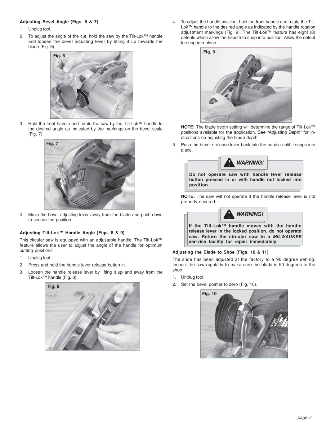
Adjusting the Blade to Shoe (Figs. 10 & 11)
The shoe has been adjusted at the factory to a 90 degree setting. Inspect the saw regularly to make sure the blade is 90 degrees to the shoe.
1.Unplug tool.
2.Set the bevel pointer to zero (Fig. 10).
Fig. 10
page 7