QUICK START GUIDE
4.1 Connecting the DX User IP to the WAN/LAN
The Ethernet connector on the DX User IP II can be used either for a 100 Mbps
To connect to a LAN/WAN, connect an Ethernet cable to the DX User IP II Ethernet port and the Network switch.
4.2 Connecting the DX User IP II to the DX Central unit
For KVM.net managed mode connect a CAT5 cable to the DX User IP II System port and to DX Central User port 1. This DX User IP II must be assigned as the Master Console – (explained in the softcopy User Guide). Where there are more than one IP devices in the DX system, (e.g. DX User IP II units or IP Access connected to a DX User unit etc), one of them must be connected to User port 1 of the DX Central. The others can be connected to any other User port number.
For Standalone and KVM.net enabled modes connect a CAT5 cable to the DX User IP II System port and to any DX Central User port.
4.3 Local User
To use the DX User IP II locally, connect a keyboard, video and mouse, as illustrated in Figure 4.
4.4 Serial cable - KVM.net managed mode only
The Serial cable is only used when this DX User IP II is assigned to be the Master Console in KVM.net managed mode (explained in the softcopy User Guide). Note! The Master Console IP device must be connected to User Port 1 of the DX Central unit.
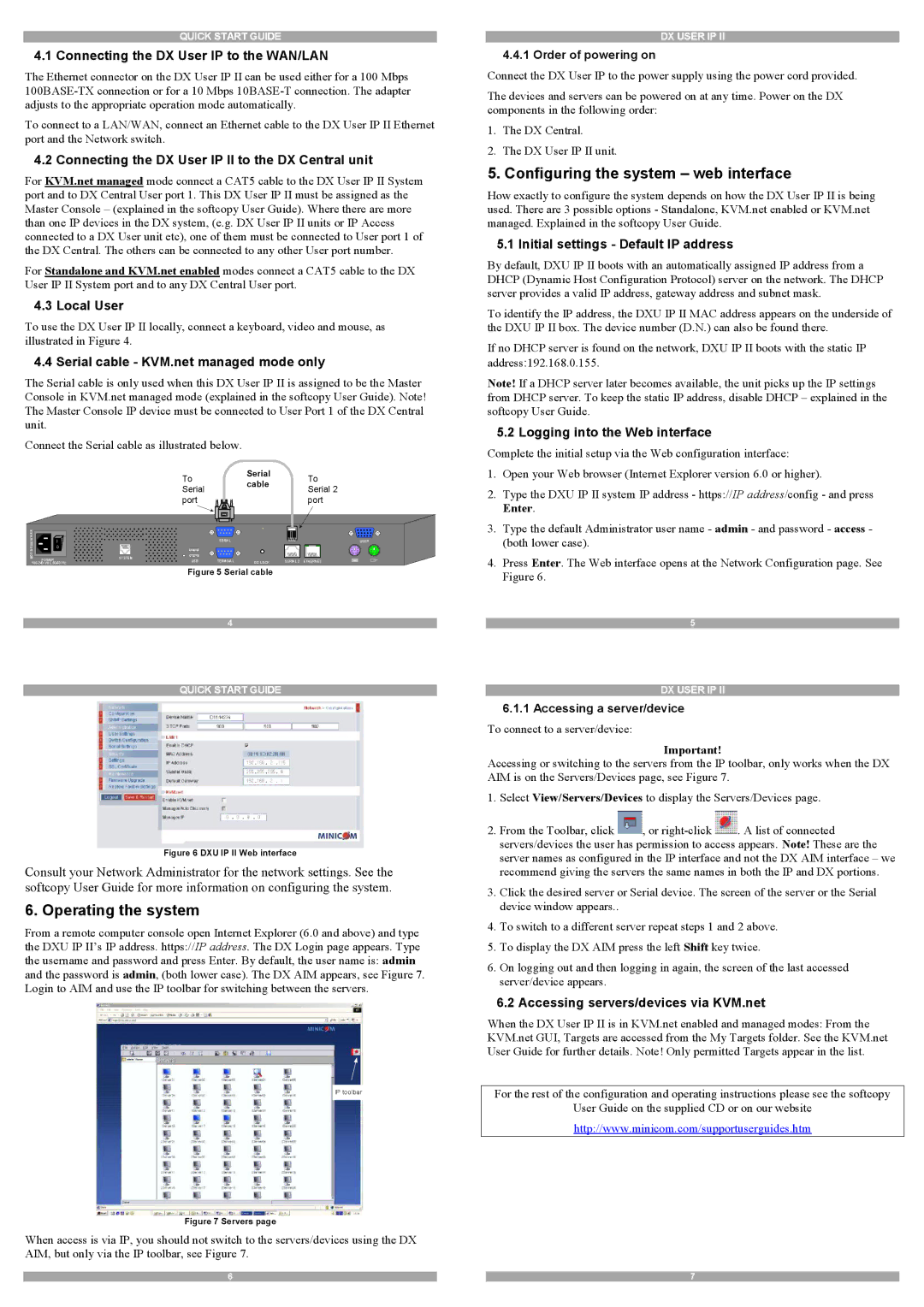
Connect the Serial cable as illustrated below.
To | Serial | To | |
cable | |||
Serial | Serial 2 | ||
| |||
port |
| port |
www. | I |
|
|
|
|
|
minicom.com |
| SERIAL |
|
| USER | |
0 |
|
|
|
|
| |
POWER | SYSTEM | TERMINAL | GO LOCK | SERIAL 2 | ETHERNET | |
USB | ||||||
Figure 5 Serial cable
4
DX USER IP II
4.4.1 Order of powering on
Connect the DX User IP to the power supply using the power cord provided.
The devices and servers can be powered on at any time. Power on the DX components in the following order:
1.The DX Central.
2.The DX User IP II unit.
5. Configuring the system – web interface
How exactly to configure the system depends on how the DX User IP II is being used. There are 3 possible options - Standalone, KVM.net enabled or KVM.net managed. Explained in the softcopy User Guide.
5.1 Initial settings - Default IP address
By default, DXU IP II boots with an automatically assigned IP address from a DHCP (Dynamic Host Configuration Protocol) server on the network. The DHCP server provides a valid IP address, gateway address and subnet mask.
To identify the IP address, the DXU IP II MAC address appears on the underside of the DXU IP II box. The device number (D.N.) can also be found there.
If no DHCP server is found on the network, DXU IP II boots with the static IP address:192.168.0.155.
Note! If a DHCP server later becomes available, the unit picks up the IP settings from DHCP server. To keep the static IP address, disable DHCP – explained in the softcopy User Guide.
5.2 Logging into the Web interface
Complete the initial setup via the Web configuration interface:
1.Open your Web browser (Internet Explorer version 6.0 or higher).
2.Type the DXU IP II system IP address - https://IP address/config - and press Enter.
3.Type the default Administrator user name - admin - and password - access - (both lower case).
4.Press Enter. The Web interface opens at the Network Configuration page. See Figure 6.
5
QUICK START GUIDE
Figure 6 DXU IP II Web interface
Consult your Network Administrator for the network settings. See the softcopy User Guide for more information on configuring the system.
6. Operating the system
From a remote computer console open Internet Explorer (6.0 and above) and type the DXU IP II’s IP address. https://IP address. The DX Login page appears. Type the username and password and press Enter. By default, the user name is: admin and the password is admin, (both lower case). The DX AIM appears, see Figure 7. Login to AIM and use the IP toolbar for switching between the servers.
IP toolbar
Figure 7 Servers page
When access is via IP, you should not switch to the servers/devices using the DX AIM, but only via the IP toolbar, see Figure 7.
DX USER IP II
6.1.1Accessing a server/device
To connect to a server/device:
Important!
Accessing or switching to the servers from the IP toolbar, only works when the DX AIM is on the Servers/Devices page, see Figure 7.
1.Select View/Servers/Devices to display the Servers/Devices page.
2.From the Toolbar, click ![]() , or
, or ![]() . A list of connected servers/devices the user has permission to access appears. Note! These are the server names as configured in the IP interface and not the DX AIM interface – we recommend giving the servers the same names in both the IP and DX portions.
. A list of connected servers/devices the user has permission to access appears. Note! These are the server names as configured in the IP interface and not the DX AIM interface – we recommend giving the servers the same names in both the IP and DX portions.
3.Click the desired server or Serial device. The screen of the server or the Serial device window appears..
4.To switch to a different server repeat steps 1 and 2 above.
5.To display the DX AIM press the left Shift key twice.
6.On logging out and then logging in again, the screen of the last accessed server/device appears.
6.2 Accessing servers/devices via KVM.net
When the DX User IP II is in KVM.net enabled and managed modes: From the KVM.net GUI, Targets are accessed from the My Targets folder. See the KVM.net User Guide for further details. Note! Only permitted Targets appear in the list.
For the rest of the configuration and operating instructions please see the softcopy
User Guide on the supplied CD or on our website
http://www.minicom.com/supportuserguides.htm
6 | 7 |