ED6200T, ED6000T specifications
The Minuteman UPS ED6000T and ED6200T are robust uninterruptible power supply (UPS) systems designed to offer reliable protection for sensitive electronic equipment. These units stand out in the market for their enhanced features, advanced technologies, and exceptional performance.The core design of the ED6000T and ED6200T integrates a pure sine wave output, ensuring compatibility with all types of devices, including sensitive electronics and critical infrastructure. This feature minimizes electrical distortion, providing protection against damage from power fluctuations. They deliver up to 6000VA and 6200VA of power respectively, making them suitable for small to medium-sized data centers, telecommunications equipment, and critical servers.
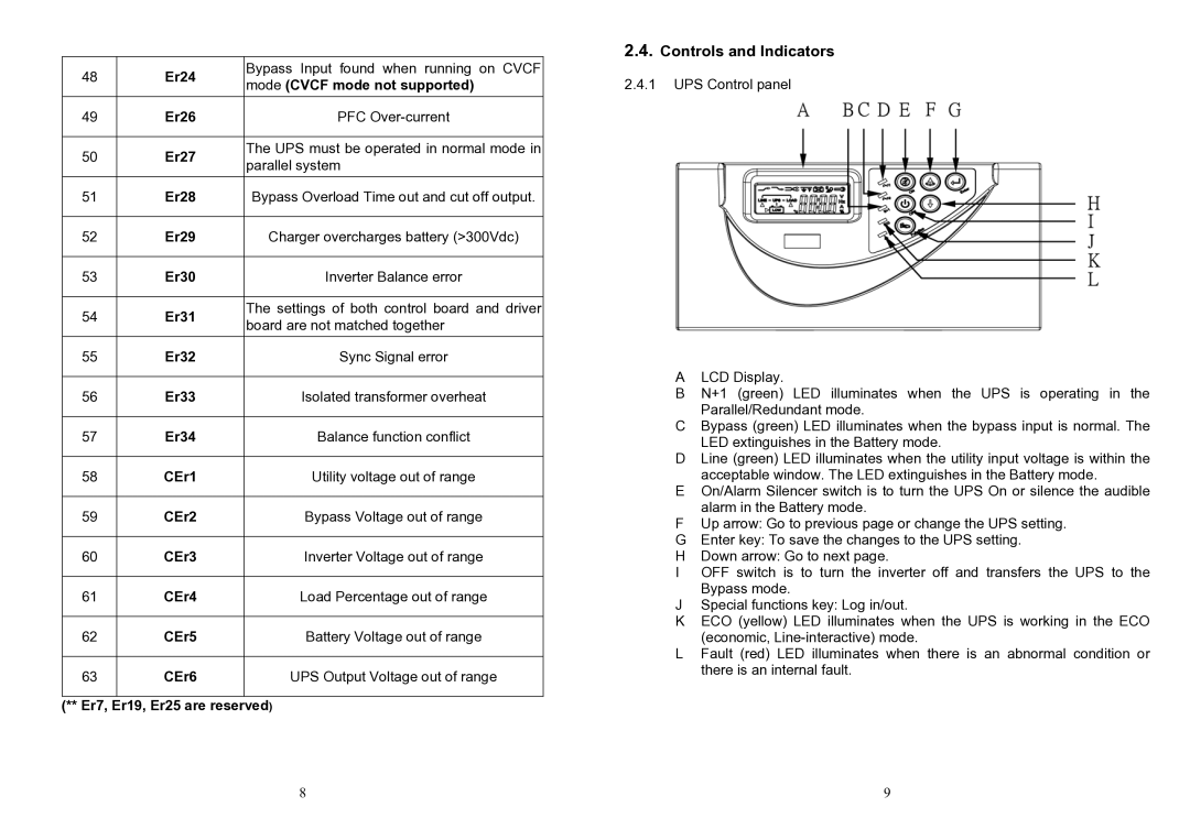
One key characteristic of these models is their comprehensive LCD display that provides real-time monitoring of UPS status, battery charge level, load percentage, and other essential diagnostics. This user-friendly interface makes it convenient for users to assess performance at a glance and manage their power protection strategies effectively.
Both models employ advanced battery management technologies, including Smart Battery Management that extends battery life through optimized charging cycles. This is crucial for maintaining reliability, especially in environments where power outages can be frequent and disruptive. The UPS units also feature an automatic voltage regulation (AVR) system that corrects minor voltage fluctuations, maintaining consistent output without switching to battery mode.
Additionally, the ED6000T and ED6200T incorporate the Minuteman Green Power UPS™ technology, designed to minimize energy consumption and reduce heat output, thus contributing to lower operational costs and environmental sustainability. With an energy-efficient design, they are not only financially beneficial but also eco-friendly.
Connectivity options are another highlight, as both models feature multiple outlets, including surge-protected and battery backup outlets, ensuring plenty of connections for various devices. They are equipped with USB and serial communication ports that allow for seamless integration with monitoring and management software, thereby enhancing their functionality in networked environments.
In conclusion, the Minuteman UPS ED6000T and ED6200T are powerful solutions for businesses seeking reliable power protection. With their pure sine wave output, advanced battery management, user-friendly interfaces, and energy-efficient designs, they represent a solid investment for safeguarding critical electronics against power interruptions.