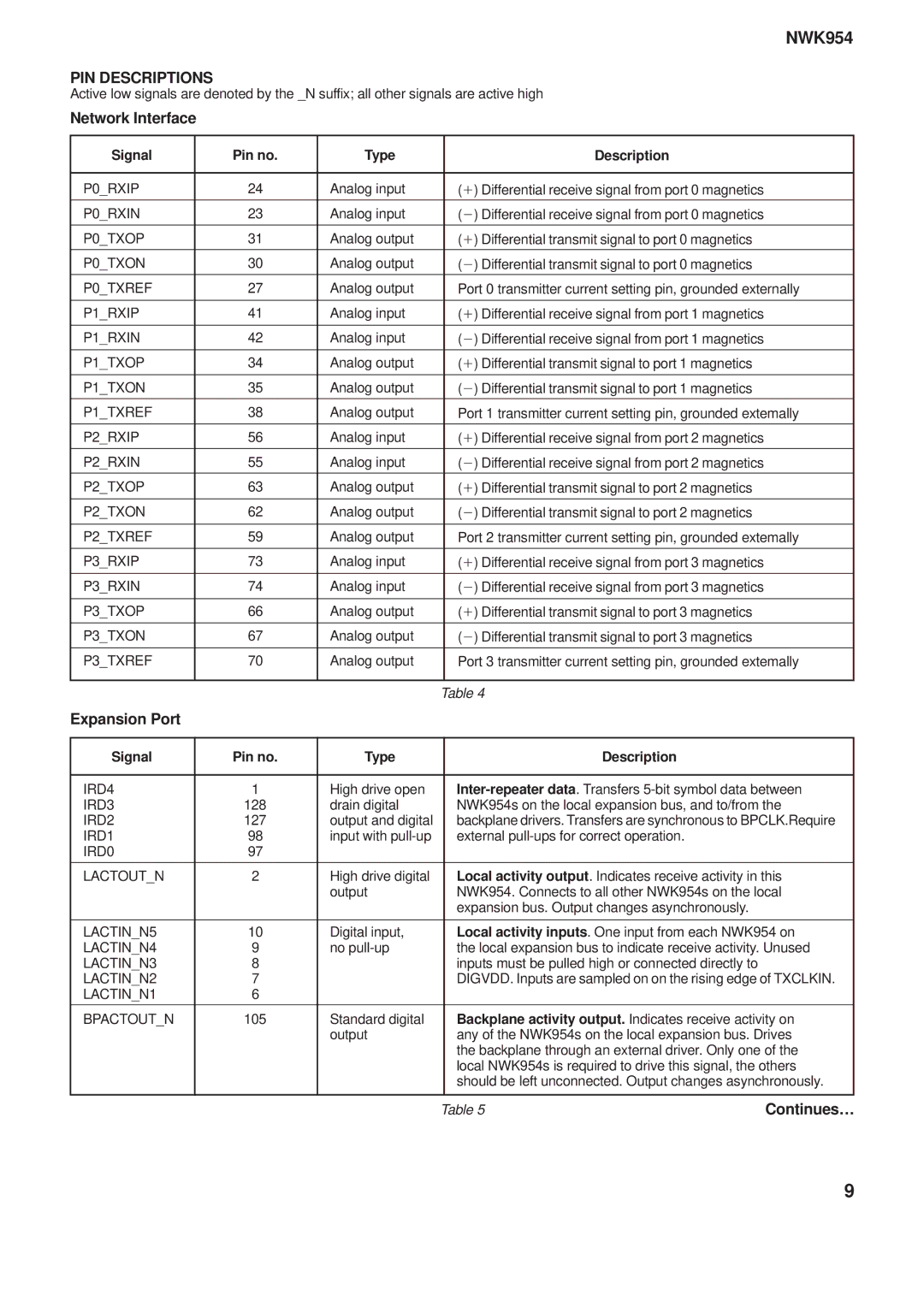
NWK954 specifications
The Mitel NWK954 is a powerful, versatile networking device designed to meet the demands of modern communication systems. This device is tailored for businesses seeking robust networking capabilities while offering a suite of features that enhance connectivity and communication efficiency.One of the standout characteristics of the Mitel NWK954 is its advanced call handling capabilities. It supports multiple concurrent calls, ensuring that organizations can handle high volumes of communication without any degradation in service quality. This feature is particularly beneficial for customer service centers and enterprises that prioritize seamless communication.
Equipped with VoIP technology, the NWK954 allows businesses to take advantage of Voice over Internet Protocol for efficient and cost-effective voice communications. Integration with existing telephony systems is simplified, enabling organizations to leverage their current infrastructure while upgrading to more sophisticated functionalities. The device supports a range of codecs, making it adaptable for various bandwidth scenarios, which is essential for ensuring voice clarity and minimizing latency.
The NWK954 is also characterized by its robust security features. It incorporates advanced encryption protocols to safeguard voice data from potential threats, ensuring secure communication across the network. This security is crucial for businesses that require confidentiality and data protection in their communication processes.
In terms of connectivity, the Mitel NWK954 offers multiple Ethernet ports that facilitate easy integration with existing networks. This flexibility allows businesses to connect various devices and systems, enhancing the overall communication ecosystem. Additionally, its support for Power over Ethernet (PoE) simplifies the installation process, eliminating the need for separate power sources for connected devices.
Another notable feature is its user-friendly interface, which simplifies management and configuration tasks. Organizations can easily monitor call activities, customize settings, and generate reports, fostering an efficient and user-centric environment.
In summary, the Mitel NWK954 is a comprehensive networking solution that boasts advanced call handling, VoIP support, robust security features, flexible connectivity options, and a user-friendly management interface. These characteristics position it as a valuable asset for businesses looking to enhance their communication capabilities and streamline operations in an increasingly interconnected world.
