100BASE-TX Receiver
The 100BASE-TX receiver recovers data from up to 140m of Cat5 UTP cable. Received data is decoded and descrambled and presented to the repeater controller as 5-bit symbols. The Transceiver Controller sequences the start-up of the receiver and does not allow data to be passed to the Repeater Controller until the receiver is fully initialized and a link is established and the descrambler is synchronized. After start-up the Transceiver Controller monitors the receiver and takes corrective action if a fault is detected.
The Signal Detect continuously monitors the level on the RXIP/RXIN differential input and indicates to the Transceiver Controller when the signal amplitude is within the range of the Equalizer. The acceptable level is considerably less than that specified in the 802.3 Standard because the NWK954 receiver is designed for recovery of signals from up to 140m of Cat5 UTP cable.
The Equalizer compensates for the signal attenuation and distortion resulting from transmission down the cable and through the isolation transformers. The Equalizer self- adjusts within 1ms of Signal Detect indicating that the incoming signal is within the acceptable range. Thereafter the Equalizer continuously adjusts to small variations in signal level without corrupting the received data.
The 100BASE-TX MLT3 code contains significant low frequency components which are not passed through the isolation transformers and cannot be restored by the Equalizer. This leads to a phenomenon known as baseline wander (BLW) which will cause an unacceptable increase in error rate if not corrected. The NWK954 employs a quantized feedback technique to restore the low frequency components and thus maintain a very low error rate even when receiving signals such as the ‘killer packet’ described in the TP-PMD specification.
The Clock Recovery circuit uses a Phase-Locked Loop (PLL) to derive a sampling clock from the incoming signal. The recovered clock runs at the symbol bit rate (nominally 125MHz) and is used to clock the MLT3 decoder and the Serial-to-Parallel converter (SIPO). The recovered clock is divided by 5 to generate the receive clock which is used to strobe received data into the Repeater Controller. The Transceiver Controller monitors behaviour of the PLL and re-initializes the receiver if lock is lost.
The SIPO and Decoder convert the received signal from serial MLT3 to 5-bit parallel NRZ.
The Link Monitor implements the 802.3 Link Monitor State Machine which indicates when a sustained signal of appropriate quality and amplitude is being received. This is the first stage in establishing a link; no data can be passed to the Repeater Controller until the Descrambler is synchronized to the incoming signal. Descrambler synchronization is established during reception of the idle pattern.After synchronization is established, the Descrambler output is continuously monitored and the Descrambler is re-synchronized if insufficient idle sequences are detected.
100BASE-TX Transmitter
The 100BASE-TX transmitter generates a 125MHz transmit clock and uses it to serialize and transmit the 5-bit symbol data input from the Repeater Controller. The Transceiver Controller sequences the start-up of the transmitter and does not allow transmission onto the twisted pair until the transmitter is fully initialized. After start-up the Transceiver Controller monitors the transmitter and takes corrective action if a fault is detected.
The Scrambler mixes the symbol data with a 2047-bit pseudo- random code, in accordance with the TP-PMD Standard. The four Scramblers in the NWK954 are seeded with different values based on the TA[4:2] input. When multiple NWK954s are cascaded to make a hub, each NWK954 should have a unique value on TA[4:2] to ensure that all of the Scramblers in the hub are seeded with different values.
The 125MHz Synthesizer employs a phase-locked loop (PLL) to generate a 125MHz timing reference from the 25MHz reference clock. The Transceiver Controller monitors behaviour of the PLL and re-initializes the Synthesizer if lock is lost.
The PISO and Encoder take NRZ-coded symbols from the Scrambler, and convert them to serial MLT3 for outputting to the TX Driver. The PISO and Encoder do not operate until the 125MHz Synthesizer is locked to the 25MHz reference. This avoids transmission of spurious signals onto the twisted pair.
The TX Driver outputs the differential signal onto the TXOP and TXON pins. It operates with 1:1 magnetics to provide impedance matching and amplification of the signal in accordance with the 802.3 specifications. The transmit current is governed by the current through the TXREF100 pin, which must be grounded through a resistor as described in Table 10.
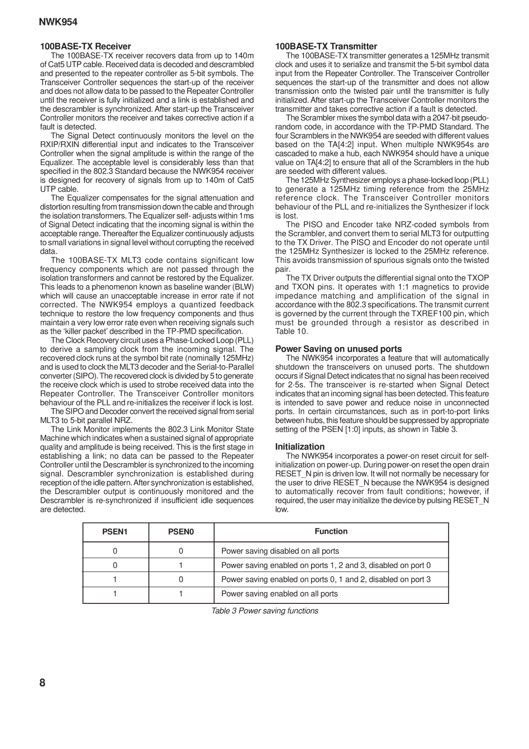
Power Saving on unused ports
The NWK954 incorporates a feature that will automatically shutdown the transceivers on unused ports. The shutdown occurs if Signal Detect indicates that no signal has been received for 2·5s. The transceiver is re-started when Signal Detect indicates that an incoming signal has been detected. This feature is intended to save power and reduce noise in unconnected ports. In certain circumstances, such as in port-to-port links between hubs, this feature should be suppressed by appropriate setting of the PSEN [1:0] inputs, as shown in Table 3.
Initialization
The NWK954 incorporates a power-on reset circuit for self- initialization on power-up. During power-on reset the open drain RESET_N pin is driven low. It will not normally be necessary for the user to drive RESET_N because the NWK954 is designed to automatically recover from fault conditions; however, if required, the user may initialize the device by pulsing RESET_N low.