Oil Pressure Safety Switch (OPS) Ð The OPS in the control circuit stops the compressor and unit, if proper oil pressure differential is not established at
Compressor Protection
CIRCUIT BREAKER Ð Calibrated trip manual reset, am- bient compensated, magnetic breaker protects against motor overload and locked rotor conditions.
CONTROL MODULE TIMER Ð This control protects com- pressor against short cycling. See Sequence of Operation on page 17.
CRANKCASE HEATER Ð This minimizes absorption of liquid refrigerant by oil in crankcase during brief or ex- tended shutdown periods.
IMPORTANT: Never open any switch or disconnect that deenergizes the crankcase heater unless unit is be- ing serviced or is to be shut down for a prolonged pe- riod. After a prolonged shutdown on a service job, en- ergize the crankcase heater for 24 hours before starting the compressor.
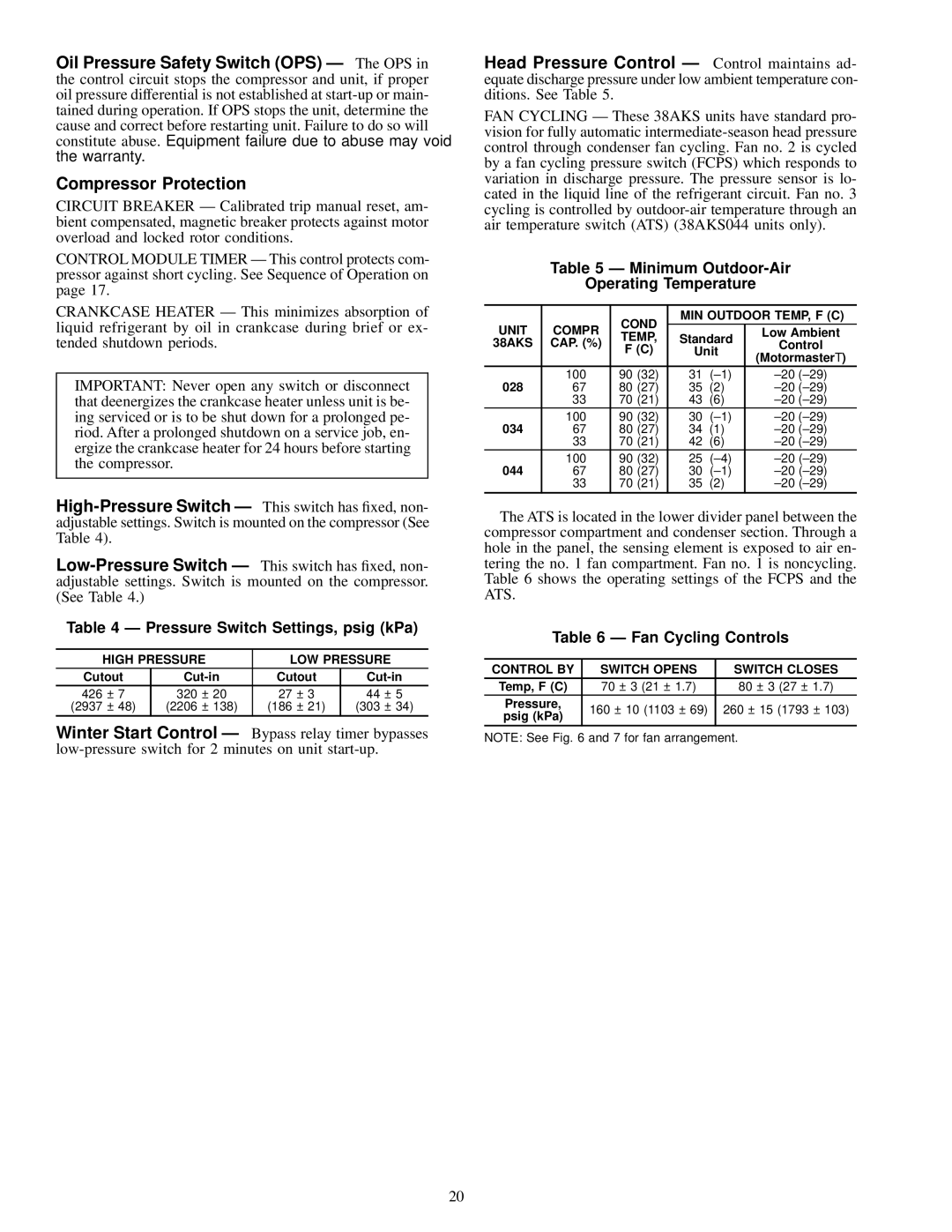
Table 4 Ð Pressure Switch Settings, psig (kPa)
| HIGH PRESSURE | LOW PRESSURE |
| |||||
Cutout | Cutout | |||||||
426 | ± 7 | 320 | ± 20 | 27 | ± 3 | 44 | ± | 5 |
(2937 | ± 48) | (2206 | ± 138) | (186 | ± 21) | (303 | ± | 34) |
Winter Start Control Ð Bypass relay timer bypasses
Head Pressure Control Ð Control maintains ad- equate discharge pressure under low ambient temperature con- ditions. See Table 5.
FAN CYCLING Ð These 38AKS units have standard pro- vision for fully automatic
Table 5 Ð Minimum Outdoor-Air
Operating Temperature
|
| COND | MIN OUTDOOR TEMP, F (C) | |||
UNIT | COMPR | TEMP, | Standard | Low Ambient | ||
38AKS | CAP. (%) | Control | ||||
F (C) | Unit | |||||
|
| (Motormaster ) | ||||
|
|
|
|
| ||
028 | 100 | 90 (32) | 31 | (±1) | ±20 (±29) | |
67 | 80 (27) | 35 | (2) | ±20 (±29) | ||
| 33 | 70 (21) | 43 | (6) | ±20 (±29) | |
034 | 100 | 90 (32) | 30 | (±1) | ±20 (±29) | |
67 | 80 (27) | 34 | (1) | ±20 (±29) | ||
| 33 | 70 (21) | 42 | (6) | ±20 (±29) | |
044 | 100 | 90 (32) | 25 | (±4) | ±20 (±29) | |
67 | 80 (27) | 30 | (±1) | ±20 (±29) | ||
| 33 | 70 (21) | 35 | (2) | ±20 (±29) | |
The ATS is located in the lower divider panel between the compressor compartment and condenser section. Through a hole in the panel, the sensing element is exposed to air en- tering the no. 1 fan compartment. Fan no. 1 is noncycling. Table 6 shows the operating settings of the FCPS and the ATS.
Table 6 Ð Fan Cycling Controls
CONTROL BY | SWITCH OPENS | SWITCH CLOSES | ||
Temp, F (C) | 70 ± 3 (21 ± 1.7) | 80 ± 3 (27 ± | 1.7) | |
Pressure, | 160 ± 10 (1103 ± 69) | 260 ± 15 (1793 | ± 103) | |
psig (kPa) | ||||
|
|
| ||
NOTE: See Fig. 6 and 7 for fan arrangement.
20