Fan Adjustment Ð Adjust fan as shown in Fig. 14.
NOTE: Dimension in ( ) is in millimeters.
Fig. 14 Ð Location of Prop on Motor Shaft from
Outside of Ori®ce Ring
Oil Charge Ð Compressors are factory charged with oil as follows:
COMPRESSOR | AMOUNT | |
pints (liters) | ||
| ||
06E9265 | 20.0 (9.4) | |
06E9275 | 20.0 (9.4) | |
06E9299 | 19.0 (9.0) |
When additional oil or a complete charge is required, use only
Petroleum Specialities Inc. . . . . . . . . . . . . . . . . . .Cryol 150 Texaco, Inc. . . . . . . . . . . . . . . . . . . . . . . . . .Capella
IMPORTANT: Do not use drained oil or use oil that has been exposed to atmosphere. Refer to Carrier Train- ing Booklet, GTAC II, Module 5, for procedures to add oil. To remove oil, isolate the compressor, reclaim internal compressor charge, and use the compressor drain plug.
Liquid Shutoff/Charging Valve Ð Valve is located inside the compressor compartment and is provided with
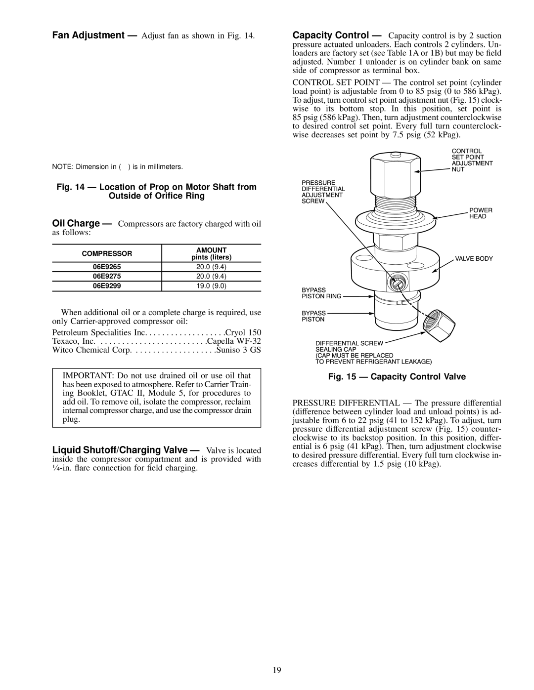
Capacity Control Ð Capacity control is by 2 suction pressure actuated unloaders. Each controls 2 cylinders. Un- loaders are factory set (see Table 1A or 1B) but may be ®eld adjusted. Number 1 unloader is on cylinder bank on same side of compressor as terminal box.
CONTROL SET POINT Ð The control set point (cylinder load point) is adjustable from 0 to 85 psig (0 to 586 kPag). To adjust, turn control set point adjustment nut (Fig. 15) clock- wise to its bottom stop. In this position, set point is 85 psig (586 kPag). Then, turn adjustment counterclockwise to desired control set point. Every full turn counterclock- wise decreases set point by 7.5 psig (52 kPag).
Fig. 15 Ð Capacity Control Valve
PRESSURE DIFFERENTIAL Ð The pressure differential (difference between cylinder load and unload points) is ad- justable from 6 to 22 psig (41 to 152 kPag). To adjust, turn pressure differential adjustment screw (Fig. 15) counter- clockwise to its backstop position. In this position, differ- ential is 6 psig (41 kPag). Then, turn adjustment clockwise to desired pressure differential. Every full turn clockwise in- creases differential by 1.5 psig (10 kPag).
19
