OPERATING PROCEDURE

PHOTOS

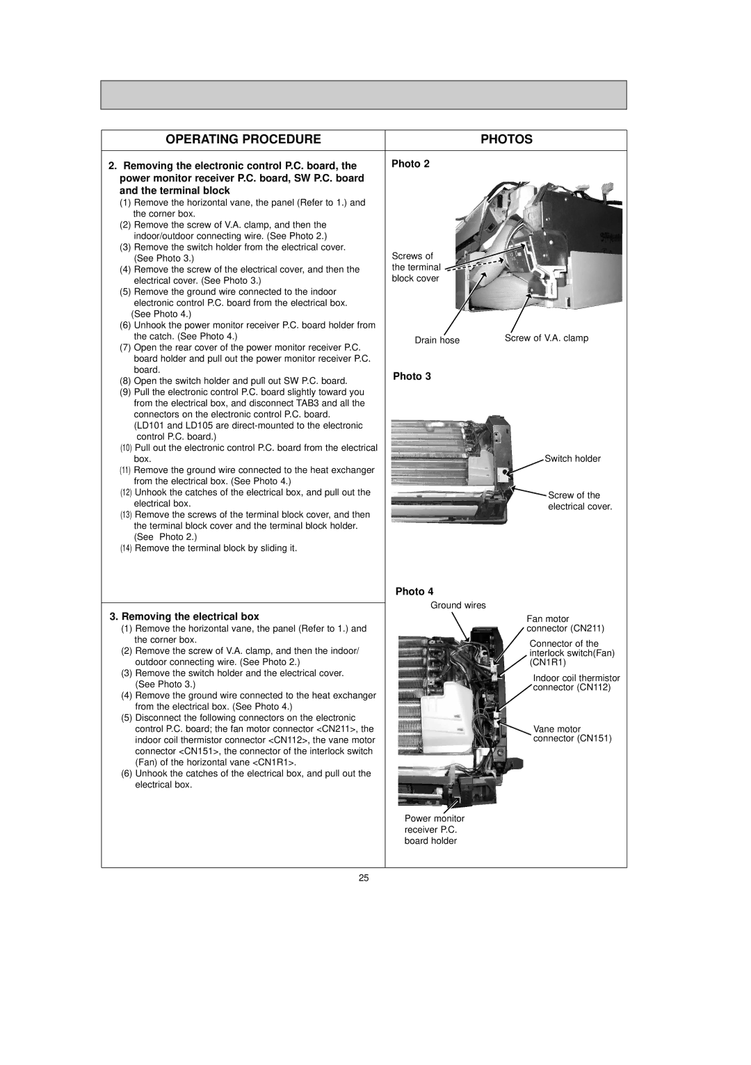
2. Removing the electronic control P.C. board, the

Photo 2

power monitor receiver P.C. board, SW P.C. board


and the terminal block


(1)Remove the horizontal vane, the panel (Refer to 1.) and the corner box.

(2)Remove the screw of V.A. clamp, and then the


indoor/outdoor connecting wire. (See Photo 2.)


(3)

Remove the switch holder from the electrical cover.

Screws of


(See Photo 3.)

(4)

Remove the screw of the electrical cover, and then the

the terminal


electrical cover. (See Photo 3.)

block cover

(5)Remove the ground wire connected to the indoor electronic control P.C. board from the electrical box.


(See Photo 4.)


(6)

Unhook the power monitor receiver P.C. board holder from


(7)

the catch. (See Photo 4.)

Drain hose

Screw of V.A. clamp

Open the rear cover of the power monitor receiver P.C.


board holder and pull out the power monitor receiver P.C.


board.

Photo 3


(8)

Open the switch holder and pull out SW P.C. board.


(9)Pull the electronic control P.C. board slightly toward you from the electrical box, and disconnect TAB3 and all the connectors on the electronic control P.C. board.

(LD101 and LD105 are direct-mounted to the electronic control P.C. board.)

(10)Pull out the electronic control P.C. board from the electrical

box.

Switch holder

(11) Remove the ground wire connected to the heat exchanger


from the electrical box. (See Photo 4.)


(12) Unhook the catches of the electrical box, and pull out the

Screw of the

electrical box.

electrical cover.


(13)Remove the screws of the terminal block cover, and then the terminal block cover and the terminal block holder. (See Photo 2.)

(14)Remove the terminal block by sliding it.


Photo 4


Ground wires

3. Removing the electrical box

Fan motor

(1)

Remove the horizontal vane, the panel (Refer to 1.) and

connector (CN211)


the corner box.

Connector of the

(2)

Remove the screw of V.A. clamp, and then the indoor/

interlock switch(Fan)


outdoor connecting wire. (See Photo 2.)

(CN1R1)

(3)

Remove the switch holder and the electrical cover.

Indoor coil thermistor


(See Photo 3.)


connector (CN112)

(4)

Remove the ground wire connected to the heat exchanger


from the electrical box. (See Photo 4.)


(5)

Disconnect the following connectors on the electronic


control P.C. board; the fan motor connector <CN211>, the

Vane motor


indoor coil thermistor connector <CN112>, the vane motor

connector (CN151)


connector <CN151>, the connector of the interlock switch


(Fan) of the horizontal vane <CN1R1>.


(6)Unhook the catches of the electrical box, and pull out the electrical box.

Power monitor receiver P.C. board holder

25

Page 25
Image 25
Mitsubishi Electronics MSZ-GA22VA, MSZ-GA25VA, MSZ-GA35VA Operating Procedure Photos, Removing the electrical box

MSZ-GA25VA, MSZ-GA35VA, MSZ-GA22VA specifications

The Mitsubishi Electronics MSZ-GA series encompasses a range of wall-mounted split systems, including the MSZ-GA22VA, MSZ-GA25VA, and MSZ-GA35VA models, designed to provide efficient heating and cooling solutions for a variety of environments. Renowned for their advanced technology and user-friendly features, these air conditioning units are a perfect match for residential and light commercial spaces.

One of the standout features of the MSZ-GA series is the innovative INVERTER technology. This system intelligently adjusts the compressor speed, ensuring that the units operate at optimal efficiency. By maintaining a consistent temperature without constant on/off cycling, this technology significantly reduces energy consumption, leading to lower electricity bills and a reduced carbon footprint.

Another major aspect of these models is their powerful yet quiet operation. The units are designed with advanced noise-reduction technology, allowing them to function at low sound levels, making them ideal for bedrooms and living rooms where disturbances should be kept to a minimum. With noise levels as low as 19 dB(A), users can enjoy a peaceful indoor environment even while the system is running.

Additionally, the MSZ-GA22VA, MSZ-GA25VA, and MSZ-GA35VA models feature an elegant and compact design, which easily integrates into any interior decor. Their sleek and minimalist aesthetics do not compromise on performance, making them a favorite among homeowners and designers alike.

The series also comes with a user-friendly remote control, enabling easy temperature adjustments and settings from across the room. For added convenience, these models include a programmable timer feature, allowing users to set the system to operate according to their schedules. This flexibility not only enhances comfort but also optimizes energy usage.

Moreover, the MSZ-GA series incorporates a powerful air filtration system that helps improve indoor air quality. Featuring a washable anti-allergy enzyme filter, these units capture dust and allergens, making the air cleaner and healthier for occupants.

With a focus on energy efficiency, quiet operation, and advanced air purification, the Mitsubishi Electronics MSZ-GA22VA, MSZ-GA25VA, and MSZ-GA35VA represent an excellent choice for anyone seeking reliable and effective climate control solutions. Whether heating or cooling, these models ensure maximum comfort while minimizing energy usage and environmental impact.