tape(WP1860) by first folding the tape in half lengthwise, adhesive side in, then trimming to 3/16î wide. Mount the assem- bly onto the forward most 3x3mm wood brace, then attach the rudder control cables to the yoke(Ni28-091), pass them back through the fuselage, through the inner two of the bottom four lightening holes in formers #4-6, then through the inner two of the four holes in the brace across former #7. Temporarily tie them off at former #10.
Engine fittings:
Attach the metal stiffening plates(Ni28- 069 and Ni28-070) to the first and second formers. Next glue on the cable brace plates(Ni28-071). Slip the pump and mag- neto gears(GR9-17) onto their shafts on the motor mounting ring(GR9-16). They are loose so they turn freely when the gear on the engine’s distributor meshes between them. Temporarily affix them with tape to avoid losing them before you install the engine. Assemble the two parts of the oil tank(Ni28-101) as in Figure 6/5 and glue this to the motor mounting ring.
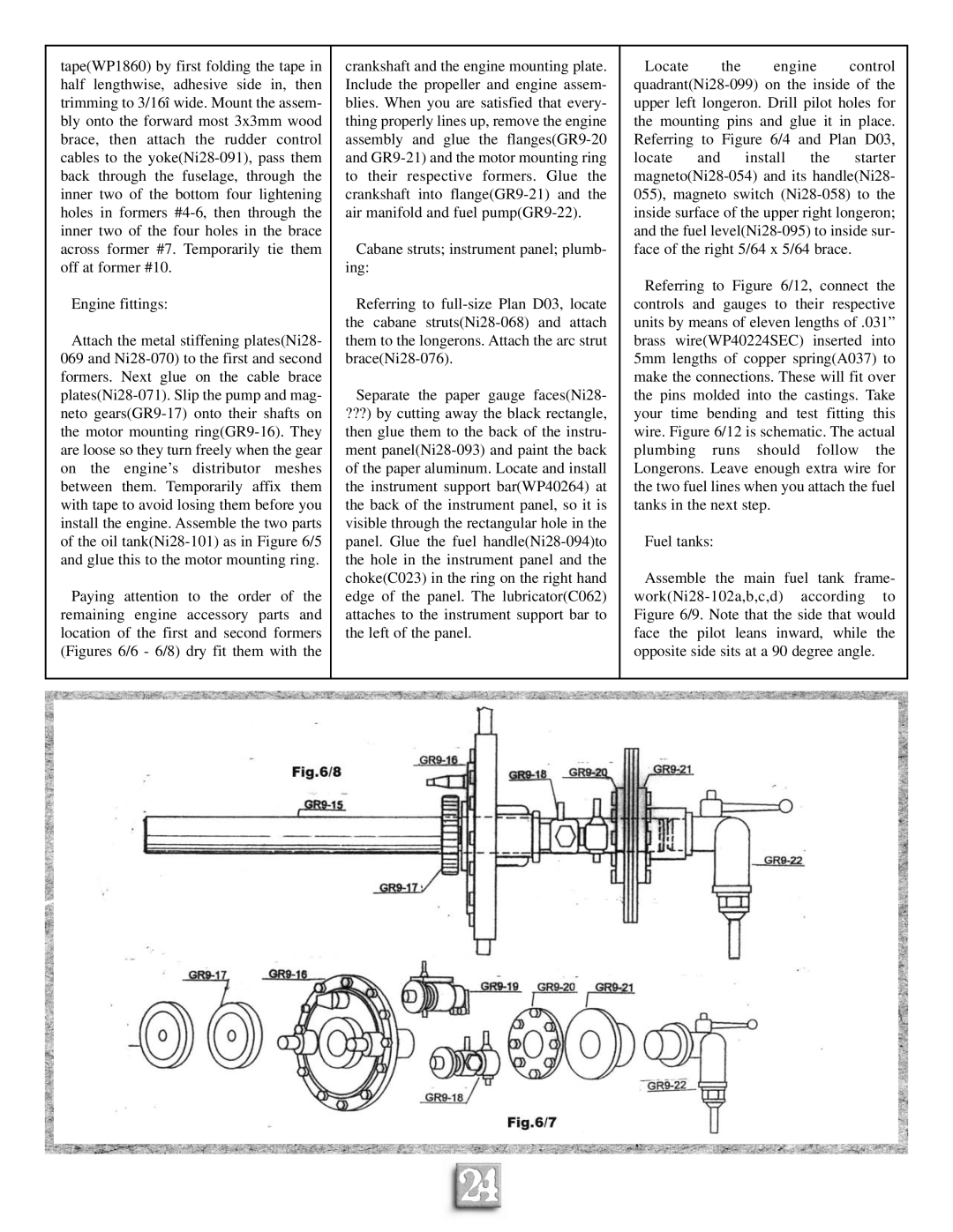
Paying attention to the order of the remaining engine accessory parts and location of the first and second formers (Figures 6/6 - 6/8) dry fit them with the
crankshaft and the engine mounting plate. Include the propeller and engine assem- blies. When you are satisfied that every- thing properly lines up, remove the engine assembly and glue the flanges(GR9-20 and GR9-21) and the motor mounting ring to their respective formers. Glue the crankshaft into flange(GR9-21) and the air manifold and fuel pump(GR9-22).
Cabane struts; instrument panel; plumb- ing:
Referring to full-size Plan D03, locate the cabane struts(Ni28-068) and attach them to the longerons. Attach the arc strut brace(Ni28-076).
Separate the paper gauge faces(Ni28-
???) by cutting away the black rectangle, then glue them to the back of the instru- ment panel(Ni28-093) and paint the back of the paper aluminum. Locate and install the instrument support bar(WP40264) at the back of the instrument panel, so it is visible through the rectangular hole in the panel. Glue the fuel handle(Ni28-094)to the hole in the instrument panel and the choke(C023) in the ring on the right hand edge of the panel. The lubricator(C062) attaches to the instrument support bar to the left of the panel.
Locate the engine control quadrant(Ni28-099) on the inside of the upper left longeron. Drill pilot holes for the mounting pins and glue it in place. Referring to Figure 6/4 and Plan D03, locate and install the starter magneto(Ni28-054) and its handle(Ni28- 055), magneto switch (Ni28-058) to the inside surface of the upper right longeron; and the fuel level(Ni28-095) to inside sur- face of the right 5/64 x 5/64 brace.
Referring to Figure 6/12, connect the controls and gauges to their respective units by means of eleven lengths of .031” brass wire(WP40224SEC) inserted into 5mm lengths of copper spring(A037) to make the connections. These will fit over the pins molded into the castings. Take your time bending and test fitting this wire. Figure 6/12 is schematic. The actual plumbing runs should follow the Longerons. Leave enough extra wire for the two fuel lines when you attach the fuel tanks in the next step.
Fuel tanks:
Assemble the main fuel tank frame- work(Ni28-102a,b,c,d) according to Figure 6/9. Note that the side that would face the pilot leans inward, while the opposite side sits at a 90 degree angle.